Page 184 of 1354

DISASSEMBLY
1. REMOVE CYLINDER BOOT SET RING AND
CYLINDER BOOT
Using a screwdriver, remove the cylinder boot")
BR0M6−01
R10631
R10633
R10634
− BRAKEFRONT BRAKE CALIPER
BR−25
1996 RAV4 (RM447U)
DISASSEMBLY
1. REMOVE CYLINDER BOOT SET RING AND
CYLINDER BOOT
Using a screwdriver, remove the cylinder boot set ring and cylin-
der boot.
2. REMOVE PISTON
(a) Put a piece of cloth or equivalent between the piston and
the caliper.
(b) Use compressed air to remove the piston from the cylin-
der.
CAUTION:
Do not place your fingers in front of the piston when using
compressed air.
3. REMOVE PISTON SEAL
Using a screwdriver, remove the piston seal.
4. REMOVE SLIDING PINS AND DUST BOOTS
(a) Remove the 2 sliding pins from the torque plate.
NOTICE:
At the time of reassembly, please refer to the following
item.
Insert the sliding pin with the sliding bushing into the upper
side.
(b) Using a screwdriver and a hammer, tap out the 2 dust
boots.
HINT:
At the time of reassembly, please refer to the following item.
Use a 21 mm socket and tap in 2 new dust boots into the torque
plate.
NOTICE:
At the time of reassembly, please refer to the following
item.
Confirm that the metal plate portion of the dust boot fits
snugly in the torque plate.
Page 185 of 1354

INSPECTION
1. MEASURE PAD LINING THICKNESS
Using a ruler, measure the pad lining thickness.
Standard th")
BR035−02
W01808
R10635
R10636
R10637
BR−26
− BRAKEFRONT BRAKE CALIPER
1996 RAV4 (RM447U)
INSPECTION
1. MEASURE PAD LINING THICKNESS
Using a ruler, measure the pad lining thickness.
Standard thickness: 12.0 mm (0.472 in.)
Minimum thickness: 1.0 mm (0.039 in.)
Replace the pad if the pad’s thickness is at the minimum thick-
ness or less, or if the pad has severe and uneven wear.
2. MEASURE DISC THICKNESS
Using a micrometer, measure the disc thickness.
Standard thickness: 18.0 mm (0.709 in.)
Minimum thickness: 16.0 mm (0.630 in.)
Replace the disc if the thickness of the disc is at the minimum
thickness or less. Replace the disc or grind it on a lathe if it is
scored or is worn unevenly.
3. MEASURE DISC RUNOUT
Using a dial indicator, measure the disc runout at a position 10
mm (0.39 in.) from the outside edge.
Maximum disc runout: 0.05 mm (0.0020 in.)
If the disc’s runout is at the maximum value or greater, check the
bearing play in the axial direction and check the axle hub runout
(See page SA−10). If the bearing play and axle hub runout are
not abnormal, adjust the disc runout or grind it on a ”On−Car”
brake lathe.
4. IF NECESSARY, ADJUST DISC RUNOUT
(a) Remove the 2 bolts and torque plate from the knuckle.
(b) Remove the hub nuts and the disc. Reinstall the disc in
the position turned 1/5 from its original position on the
hub. Install and torque the hub nuts.
Torque: 103 N·m (1,050 kgf·cm, 76 ft·lbf)
(c) Remeasure the disc runout. Make a note of the runout
and the disc’s position on the hub.
(d) Repeat (b) and (c) until the disc is installed on the 3 re-
maining hub positions.
�If the minimum runout recorded in (b) and (c) is less
than 0.05 mm (0.0020 in.), install the disc in that
position.
�If the minimum runout recorded in (b) and (c) is
greater than 0.05 mm (0.0020 in.), replace the disc
and repeat step 3.
(e) Install the torque plate and torque the mounting bolts.
Torque: 107 N·m (1,090 kgf·cm, 79 ft·lbf)
Page 188 of 1354
BR03E−02
W01385
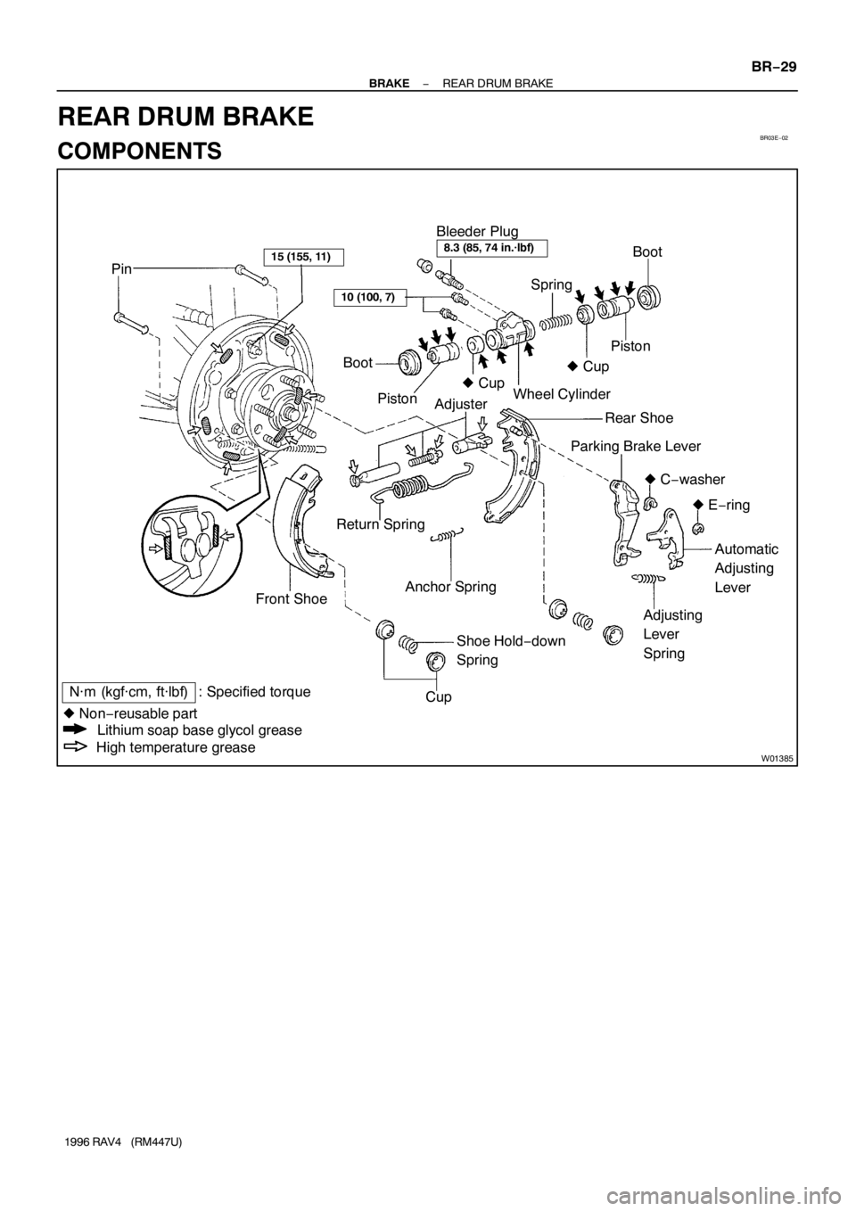
PinBoot
� Cup Bleeder Plug
Piston Spring
AdjusterWheel Cylinder
Rear Shoe
Parking Brake Lever
� C−washer
� E−ring
Automatic
Adjusting
Lever
Adjusting
Lever
Spring Anchor Spring
Shoe Hold−down
Spring Return Spring
Front ShoeBoot
Piston� Cup
Cup15 (155, 11)8.3 (85, 74 in.·lbf)
10 (100, 7)
N·m (kgf·cm, ft·lbf) : Specified torque
� Non−reusable part
Lithium soap base glycol grease
High temperature grease
− BRAKEREAR DRUM BRAKE
BR−29
1996 RAV4 (RM447U)
REAR DRUM BRAKE
COMPONENTS
Page 190 of 1354
Z13290
SST
R10699
R10700
SST
BR0370
− BRAKEREAR DRUM BRAKE
BR−31
1996 RAV4 (RM447U)
5. REMOVE REAR SHOE
(a) Using SST, remove the shoe hold−down spring, cups and
pin.
SST 09718−00010
(b) Using a screwdriver, disconnect the parking brake cable
from the anchor plate.
(c) Using pliers, disconnect the parking brake cable from the
lever and remove the rear shoe together with the adjuster.
6. REMOVE ADJUSTER FROM REAR SHOE
(a) Remove the adjusting lever spring.
(b) Remove the adjuster together with the return spring.
7. DISCONNECT BRAKE LINE FROM WHEEL CYL-
INDER
Using SST, disconnect the brake line. Use a container to catch
the brake fluid.
SST 09023−00100
Torque: 15 N·m (155 kgf·cm, 11 ft·lbf)
8. REMOVE WHEEL CYLINDER
Remove the 2 bolts and the wheel cylinder.
Torque: 10 N·m (100 kgf·cm, 7 ft·lbf)
9. DISASSEMBLE WHEEL CYLINDER
Remove these parts from the wheel cylinder.
�2 boots
�2 pistons
�2 piston cups
�Spring
Page 197 of 1354
BR1NN−01
W04219
Power Steering
Fluid Reservoir Actuator Bracket Cushion ABS Actuator Cushion Bolt Cushion
5 (55, 48 in.·lbf)
19 (195, 14)
19 (195, 14)
15 (155, 11)
N·m (kgf·cm, ft·lbf)
: Specified torque
19 (195, 14)
2WD BR−38
− BRAKEABS ACTUATOR
1996 RAV4 (RM447U)
COMPONENTS
Page 199 of 1354
BR0MA−03
BR−40
− BRAKEABS ACTUATOR
1996 RAV4 (RM447U)
REMOVAL
1. DISCONNECT BRAKE LINES
Using SST, disconnect the 6 brake lines from the ABS actuator.
SST 09023−00100
Torque: 15 N·m (155 kgf·cm, 11 ft·lbf)
2. DISCONNECT POWER STEERING FLUID RES-
ERVOIR
(a) Remove the bolt and disconnect the PS hose from the ac-
tuator bracket.
(b) Disconnect the PS fluid reservoir.
3. REMOVE ABS ACTUATOR ASSEMBLY
(a) Disconnect the 2 connectors.
(b) Remove the 3 bolts and ABS actuator assembly.
Torque: 19 N·m (195 kgf·cm, 14 ft·lbf)
4. 2WD
REMOVE ABS ACTUATOR
Remove the 2 nuts and actuator from the actuator bracket.
Torque: 5 N·m (55 kgf·cm, 48 in.·lbf)
5. 4WD
REMOVE ABS ACTUATOR
Remove the 3 nuts and actuator from the actuator bracket.
Torque: 5 N·m (55 kgf·cm, 48 in.·lbf)
6. 2WD
REMOVE 2 CUSHION BOLTS AND 3 CUSHIONS
7. 4WD
REMOVE 3 HOLDERS AND 3 CUSHIONS
Page 201 of 1354
W04167
Sensor Rotor
Front Speed Sensor
N·m (kgf·cm, ft·lbf): Specified torque
8 (80, 69 in.·lbf)
5 (55, 48 in.·lbf)
BR03V−08
BR−42
− BRAKEFRONT SPEED SENSOR
1996 RAV4 (RM447U)
FRONT SPEED SENSOR
COMPONENTS
Page 202 of 1354
BR03W−04
R10728
R10703
− BRAKEFRONT SPEED SENSOR
BR−43
1996 RAV4 (RM447U)
REMOVAL
1. DISCONNECT SPEED SENSOR CONNECTOR
(a) Remove the fender liner.
(b) Disconnect the speed sensor connector.
2. REMOVE SPEED SENSOR
(a) Remove the 4 clamp bolts holding the sensor harness to
the body, shock absorber and steering knuckle.
Torque: 5 N·m (55 kgf·cm, 48 in.·lbf)
(b) Remove the speed sensor from the steering knuckle.
Torque: 8 N·m (80 kgf·cm, 69 in.·lbf)

5. REMOVE REAR SHOE
(a) Using SST, remove the shoe hold−down spring, cups and
pin.
SST 09718−00010
(b) Usi")

19 (195, 14)
19 (195, 14)
15 (155, 11)
N·m (kgf·cm, ft·lbf)
: Specifi")

REMOVAL
1. DISCONNECT BRAKE LINES
Using SST, disconnect the 6 brake lines from the ABS actuator.
SST 09023−00100
Torque: 15 N·m (155 kg")
: Specified torque
8 (80, 69 in.·lbf)
5 (55, 48 in.·lbf)
BR03V−08
BR−42
− BRAKEFRONT SPEED SENSOR
1996 RAV4 (RM447U)
FRONT SPEED")

REMOVAL
1. DISCONNECT SPEED SENSOR CONNECTOR
(a) Remove the fender liner.
(b) Disconnect the speed sensor connector.
2")