Page 99 of 1354
BO0ZO−01
V00005
Shape (Example)
Removal / Installation
Clip RemoverPliers
Screwdriver
Scraper
− BODYCLIP
BO−1
1996 RAV4 (RM447U)
CLIP
REPLACEMENT
The removal and installation methods of typical clips used in body parts are shown in the table below.
HINT:
If the clip is damaged during the operation, always replace it with a new clip.
Page 180 of 1354

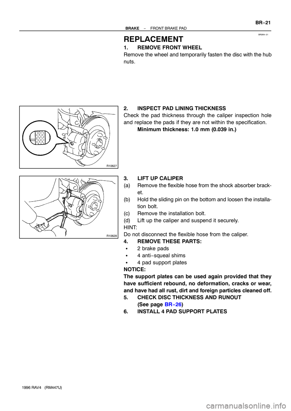
BR0M4−01
R10627
R10628
− BRAKEFRONT BRAKE PAD
BR−21
1996 RAV4 (RM447U)
REPLACEMENT
1. REMOVE FRONT WHEEL
Remove the wheel and temporarily fasten the disc with the hub
nuts.
2. INSPECT PAD LINING THICKNESS
Check the pad thickness through the caliper inspection hole
and replace the pads if they are not within the specification.
Minimum thickness: 1.0 mm (0.039 in.)
3. LIFT UP CALIPER
(a) Remove the flexible hose from the shock absorber brack-
et.
(b) Hold the sliding pin on the bottom and loosen the installa-
tion bolt.
(c) Remove the installation bolt.
(d) Lift up the caliper and suspend it securely.
HINT:
Do not disconnect the flexible hose from the caliper.
4. REMOVE THESE PARTS:
�2 brake pads
�4 anti−squeal shims
�4 pad support plates
NOTICE:
The support plates can be used again provided that they
have sufficient rebound, no deformation, cracks or wear,
and have had all rust, dirt and foreign particles cleaned off.
5. CHECK DISC THICKNESS AND RUNOUT
(See page BR−26)
6. INSTALL 4 PAD SUPPORT PLATES
Page 207 of 1354

Manual NamePub. No.
�3S-FE Engine Repair Manual
�TOYOTA RAV4 Chassis and Body Repair
Manual
�TOYOTA RAV4 Chassis and Body Repair
Manual Supplement
�TOYOTA RAV4 Electrical Wiring
Diagram
�TOYOTA RAV4 Electrical Wiring
Diagram Supplement
�TOYOTA RAV4 New Car Features
�TOYOTA RAV4 Repair Manual
For Collision Damage
�Fundamental Painting Procedures
�Fundamental Body Repair ProceduresBRM024E
BRM002E NCF108E
BRM045E EWD234F EWD206Y RM454E RM395E
FOREWORD
This repair manual has been prepared to provide essential
information on body panel repair methods (including cutting
and welding operations, but excluding painting) for the
TOYOTA RAV4 5-DOOR.
Applicable models: SXA11 series
This manual consists of body repair methods, exploded diaœ
grams and illustrations of the body components and other
information relating to body panel replacement such as hanœ
dling precautions, etc. However, it should be noted that the
front fenders of the TOYOTA model is bolted on and require
no welding.
When repairing, don't cut and join areas that are not shown in
this manual. Only work on the specified contents to maintain
body strength.
Body construction will sometimes differ depending on specifiœ
cations and country of destination. Therefore, please keep in
mind that the information contained herein is based on veœ
hicles for general destinations.
For the repair procedures and specifications other than colliœ
sion-damaged body components of the TOYOTA RAV 4
5-DOOR refer to the following repair manuals.
If you require the above manuals, please contact your TOœ
YOTA Dealer.
All information contained in this manual is the most up-to-
date at the time of publication. However, specifications and
procedures are subject to change without prior notice.
TOYOTA MOTOR CORPORATION
RM401E
Page 208 of 1354

mm in.
150
2505.91
9.84
QUARTER PANEL (CUT)
QUARTER PANEL
RH:
LH:
1. Cut and join the parts at the location shown above.
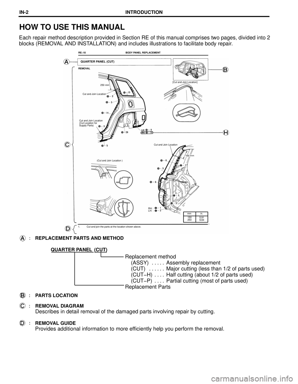
HOW TO USE THIS MANUAL
Each repair method description provided in Section RE of this manual comprises two pages, divided into 2
blocks (REMOVAL AND INSTALLATION) and includes illustrations to facilitate body repair.
RE-10
BODY PANEL REPLACEMENT
REMOVAL
[Cut and Join Location]
250 mm
Cut and Join Location
Cut and Join Location
(Cut Location for
Supply Parts)
Cut and Join Location
(Cut and Join Location )
Braze
REPLACEMENT PARTS AND METHOD
(CUT)
Replacement method
(ASSY) Assembly replacement. . . . .
(CUT) Major cutting (less than 1/2 of parts used). . . . . .
(CUT-H) Half cutting (about 1/2 of parts used). . . .
(CUT-P) Partial cutting (most of parts used). . . .
Replacement Parts
PARTS LOCATION
REMOVAL DIAGRAM
Describes in detail removal of the damaged parts involving repair by cutting.
REMOVAL GUIDE
Provides additional information to more efficiently help you perform the removal.
INTRODUCTIONINœ2
Page 209 of 1354
mm in.
5
0.20
1. Before temporarily installing the new parts, apply
body sealer to the wheel arch.
HINT:
1) Apply body sealer about 5 mm (0.20in.) from the
flange, avoiding any oozing.
2) Apply sealer evenly, about 3 - 4 mm (0. 12 -
0.16in.) in diameter.
3) For other sealing points, refer to section AR.
SYMBOLS
See page IN-4.
RH:
LH: BODY PANEL REPLACEMENT
RE-11
INSTALLATION
Butt Weld
Body Sealer
Butt Weld
Butt weld
Body sealer
Braze
about 5 mm
RH:
LH:
2. Temporarily install the new parts and check the fit
of the rear door, back door and rear combination
light.
INSTALLATION DIAGRAM
Describes in detail installation of the new parts involving repair by welding and/or cutting, but exœ
cluding painting.
INSTALLATION GUIDE
Provides additional information to more efficiently help you perform the installation.
ILLUSTRATION OF WELD POINTS
Weld method and panel position symbols.
See page IN-5.
INTRODUCTIONINœ3
Page 212 of 1354
Airbag SensorInflator Sensor Lock Release BoltBagSteering Wheel PadSteering Wheel Bolt Cap Airbag SensorInflatorBag
HANDLING PRECAUTIONS ON RELATED COMPONENTS
1. SRS AIRBAG
The TOYOTA RAV4 is equipped with an SRS (Supplemental Restraint System) airbag as an option.
Failure to carry out service operations in the correct sequence could cause the airbag system to unexœ
pectedly deploy during servicing, possibly leading to a serious accident.
Further, if a mistake is made in servicing the airbag system, it is possible the airbag may fail to operate
when required.
Before performing servicing (including removal or installation of parts, inspection or replacement), be
sure to read the following items carefully, then follow the correct procedure described in the repair
manual for relevant model.
Location of Components
INTRODUCTIONINœ6
Page 240 of 1354
mm in
30
801.18
3.15
CENTER BODY PILLAR (CUT)
REMOVAL
Cut and Join Location
(Cut Location for Supply Parts)
[Cut and Join Location]
80 mm
30 mm
30 mm
Cut and Join Location
Cut and Join Location
Cut and Join Location
(Cut Location for Supply Parts)
[Cut and Join Location]
1. Cut and join the parts at the locations shown
above.
BODY PANEL REPLACEMENTREœ2
Page 241 of 1354
INSTALLATION
Butt Weld
Center Body Pillar Reinforcement
Center Body Inner
Pillar
Butt Weld
Butt Weld
Butt Weld
Butt WeldButt Weld
2. Temporarily install the new parts and meaœ
sure each part in accordance with the body
dimension diagram.
3. Before welding the new parts, check the fit of
the front door and rear door. 1. Before temporarily installing the new parts,
weld the inner pillar and center pillar reinœ
forcement with standard points.
BODY PANEL REPLACEMENTREœ3