Page 1070 of 1399

REMOVAL
1. REMOVE FRONT WHEEL
2. REMOVE BRAKE CALIPER (See page BR−25 )
3. REMOVE FLANGE
(a) Using a")
SA1UB−01
SA2635
SST
−
SUSPENSION AND AXLE FRONT AXLE HUB
SA−7
1996 LAND CRUISER (RM451U)
REMOVAL
1. REMOVE FRONT WHEEL
2. REMOVE BRAKE CALIPER (See page BR−25 )
3. REMOVE FLANGE
(a) Using a screwdriver and hammer, remove the grease cap
from the flange.
(b) Using a snap ring expander, remove the snap ring.
(c) Loosen the 6 mounting nuts.
(d) Using a brass bar and hammer, tap on the 6 bolts heads and remove the 6 cone washers, plate washers and nuts.
(e) Remove the flange.
(f) Remove the gasket.
4. REMOVE AXLE HUB WITH DISC
(a) Using a screwdriver, release the lock washer.
(b) Using SST, remove the lock nut. SST 09607−60020
(c) Remove the lock washer.
(d) Using SST, remove the adjusting nut and thrust washer.
SST 09607−60020
(e) Remove the hub and disc together with the outer bearing.
5. REMOVE OIL SEAL AND INNER BEARING
(a) Using SST, remove the oil seal. SST 09308−00010
(b) Remove the inner bearing from the hub.
Brought to you by BirfMark
Brought to you by BirfMark
Version 1.11 - 03/16/2010
Page 1071 of 1399

REMOVAL
1. REMOVE FRONT WHEEL
2. REMOVE BRAKE CALIPER (See page BR−25 )
3. REMOVE FLANGE
(a) Using a")
SA1UB−01
SA2635
SST
−
SUSPENSION AND AXLE FRONT AXLE HUB
SA−7
1996 LAND CRUISER (RM451U)
REMOVAL
1. REMOVE FRONT WHEEL
2. REMOVE BRAKE CALIPER (See page BR−25 )
3. REMOVE FLANGE
(a) Using a screwdriver and hammer, remove the grease cap
from the flange.
(b) Using a snap ring expander, remove the snap ring.
(c) Loosen the 6 mounting nuts.
(d) Using a brass bar and hammer, tap on the 6 bolts heads and remove the 6 cone washers, plate washers and nuts.
(e) Remove the flange.
(f) Remove the gasket.
4. REMOVE AXLE HUB WITH DISC
(a) Using a screwdriver, release the lock washer.
(b) Using SST, remove the lock nut. SST 09607−60020
(c) Remove the lock washer.
(d) Using SST, remove the adjusting nut and thrust washer.
SST 09607−60020
(e) Remove the hub and disc together with the outer bearing.
5. REMOVE OIL SEAL AND INNER BEARING
(a) Using SST, remove the oil seal. SST 09308−00010
(b) Remove the inner bearing from the hub.
Brought to you by BirfMark
Brought to you by BirfMark
Version 1.11 - 03/16/2010
Page 1073 of 1399
R08416
SA−10
−
SUSPENSION AND AXLE FRONT AXLE HUB
1996 LAND CRUISER (RM451U)
(e) Secure the lock nut by bending one of the lock washer
teeth inward and the other lock washer teeth outward.
7. INSTALL FLANGE
(a) Place a new gasket in position on the axle hub.
(b) Apply MP grease to the inner flange splines.
(c) Install the flange to the axle hub.
(d) Install the 6 cone washers, plate washers and nuts.
(e) Torque the 6 nuts.
Torque: 35 N·m (360 kgf·cm, 26 ft·lbf)
(f) Install the bolt in the axle shaft and pull it out.
(g) Using a snap ring expander, install a new snap ring.
(h) Remove the bolt.
(i) Coat inside of the cap with MP grease.
(j) Install the cap to the flange.
8. INSTALL BRAKE CALIPER (See page BR−29 )
9. INSTALL FRONT WHEEL Torque:
Steel wheel: 147 N·m (1,500 kgf·cm, 109 ft·lbf)
Alumimum wheel: 103 N·m (1,050 kgf·cm, 76 ft·lbf)
10. BLEED BRAKE LINE
Brought to you by BirfMark
Brought to you by BirfMark
Version 1.11 - 03/16/2010
Page 1074 of 1399
SA1UE−01
−
SUSPENSION AND AXLE FRONT WHEEL HUB BOLT
SA−11
868
Author�: Date�:
1996 LAND CRUISER (RM451U)
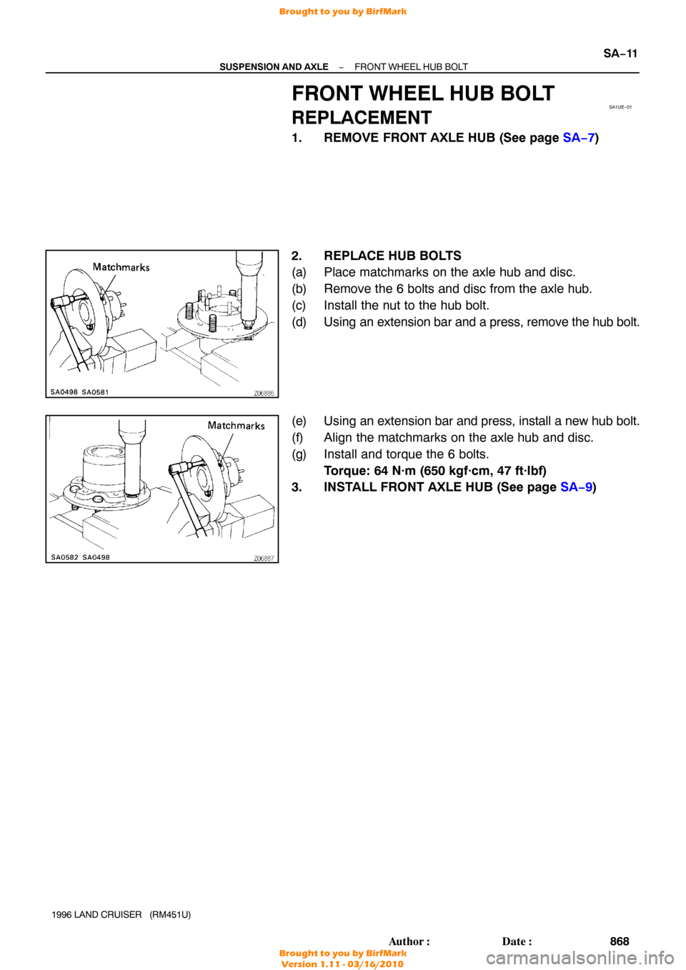
FRONT WHEEL HUB BOLT
REPLACEMENT
1. REMOVE FRONT AXLE HUB (See page SA−7 )
2. REPLACE HUB BOLTS
(a) Place matchmarks on the axle hub and disc.
(b) Remove the 6 bolts and disc from the axle hub.
(c) Install the nut to the hub bolt.
(d) Using an extension bar and a press, remove the hub bolt.
(e) Using an extension bar and press, install a new hub bolt.
(f) Align the matchmarks on the axle hub and disc.
(g) Install and torque the 6 bolts. Torque: 64 N·m (650 kgf·cm, 47 ft·lbf)
3. INSTALL FRONT AXLE HUB (See page SA−9)
Brought to you by BirfMark
Brought to you by BirfMark
Version 1.11 - 03/16/2010
Page 1076 of 1399

REMOVAL
1. REMOVE FRONT AXLE HUB (See page SA−7 )
2. REMOVE AB")
SA1UG−01
W00495
SA2644
SST
R08383
R13137
−
SUSPENSION AND AXLE STEERING KNUCKLE AND AXLE SHAFT
SA−13
1996 LAND CRUISER (RM451U)
REMOVAL
1. REMOVE FRONT AXLE HUB (See page SA−7 )
2. REMOVE ABS SPEED SENSOR
Remove the 2 bolts and disconnect the speed sensor from the
steering knuckle.
3. REMOVE DUST SEAL AND DUST COVER
Remove the 8 bolts, dust seal, dust cover and gasket.
4. REMOVE KNUCKLE SPINDLE
(a) Using a brass bar and hammer, tap the knuckle spindle of the steering knuckle.
(b) Remove the knuckle spindle and gasket.
5. REMOVE AXLE SHAFT
Position one flat part of the outer shaft upward and remove the
axle shaft.
6. DISCONNECT TIE ROD FROM KNUCKLE ARM
(a) Remove the cotter pin and nut.
(b) Using SST, disconnect the tie rod from the knuckle arm. SST 09611 −22012
7. REMOVE OIL SEAL SET
(a) Remove the 6 bolts from the end retainer.
(b) Remove these parts from the steering knuckle:
�Oil seal end retainer
�Felt dust seal
�Rubber seal
�Steel ring
8. REMOVE KNUCKLE ARM AND BEARING CAP
(a) Remove the 2 bolts and plate washers from the bearing cap.
(b) Remove the 4 nuts from the knuckle arm.
(c) Using a brass bar and hammer, tap on the 4 bolts heads and remove the 4 cone washers.
Brought to you by BirfMark
Brought to you by BirfMark
Version 1.11 - 03/16/2010
Page 1081 of 1399

(h) Install the 2 plate washers and")
R13138
90°
Z15222
Molybdenum
Disulfide
Lithium
Base Grease
NIGI No.2
SA−18
−
SUSPENSION AND AXLE STEERING KNUCKLE AND AXLE SHAFT
1996 LAND CRUISER (RM451U)
(h) Install the 2 plate washers and bolts.
Torque: 96 N·m (980 kgf·cm, 71 ft·lbf)
6. MEASURE BEARINGS PRELOAD
Using a spring tension gauge, measure the preload. Preload (at starting):
25 − 44 N (2.5 − 4.5 kgf, 5.6 − 9.9 lbf)
7. ADJUST BEARING PRELOAD
(a) Remove the bearing cap and knuckle arm (See page SA−13 ).
(b) Select the adjusting shim. Adjusting shim thickness
Thickness mm (in.)Thickness mm (in.)
0.1 (0.004)0.5 (0.020)
0.2 (0.008)1.0 (0.039)
(c) Install the bearing cap and knuckle arm (See page SA−17 ).
8. CONNECT TIE ROD TO KNUCKLE ARM
Torque the nut and secure it with a new cotter pin. Torque: 91 N·m (925 kgf·cm, 67 ft·lbf)
9. INSTALL OIL SEAL END RETAINER TO KNUCKLE ARM
Install the oil seal end retainer to steering knuckle with the 6
bolts. Torque: 5.4 N·m (55 kgf·cm, 48 in.·lbf)
10. INSTALL AXLE SHAFT
Position one flat part of the outer shaft upward and install the
shaft.
11. PACK MOLYBDENUM DISULFIDE LITHIUM BASE GREASE, NLGI NO.2
Pack molybdenum disulfide lithium base grease, NLGI No.2
into the knuckle to about 3 fourths of the knuckle.
12. INSTALL KNUCKLE SPINDLE, DUST COVER WITH
GASKETS AND DUST SEAL
(a) Place a new gasket in the position on the knuckle and
install the spindle.
(b) Place the dust cover, dust seal and a new gasket on the spindle.
Brought to you by BirfMark
Brought to you by BirfMark
Version 1.11 - 03/16/2010
Page 1082 of 1399
−
SUSPENSION AND AXLE STEERING KNUCKLE AND AXLE SHAFT
SA−19
1996 LAND CRUISER (RM451U)
(c) Torque the 8 bolts.
Torque: 47 N·m (475 kgf·cm, 34 ft·lbf)
13. CONNECT ABS SPEED SENSOR
Connect the speed sensor and 2 bolts to the steering knuckle.
Torque: 18 N·m (185 kgf·cm, 13 ft·lbf)
14. INSTALL AXLE HUB (See page SA−9)
15. CHECK FRONT WHEEL ALIGNMENT (See page SA−4 )
16. CHECK ABS SPEED SENSOR SIGNAL (See page DI−190 )
Brought to you by BirfMark
Brought to you by BirfMark
Version 1.11 - 03/16/2010
Page 1093 of 1399

6. w/o DIFFERENTIAL LOCK:
CHECK SIDE GEAR BACKLASH
Using a dial indicator, measure")
SA2442
R13332
SA2206
Z10098
SA−30
−
SUSPENSION AND AXLE FRONT DIFFERENTIAL CARRIER
1996 LAND CRUISER (RM451U)
6. w/o DIFFERENTIAL LOCK:
CHECK SIDE GEAR BACKLASH
Using a dial indicator, measure the side gear backlash with
holding one pinion gear toward the case.
Backlash: 0.05 − 0.20 mm (0.0020 − 0.0079 in.)
If the backlash is not within the specification, install the correct
thrust washers (See page .SA−35 ).
7. CHECK TOOTH CONTACT BETWEEN RING GEAR AND DRIVE PINION (See page SA−35 )
8. w/ DIFFERENTIAL LOCK: REMOVE ACTUATOR
(a) Remove the bolt and actuator from the differential carrier.
(b) Remove the O−ring.
9. w/ DIFFERENTIAL LOCK: REMOVE INDICATOR SWITCH
Remove the indicator switch and gasket.
10. w/ DIFFERENTIAL LOCK:
REMOVE SHIFT FORK SHAFT
(a) Using a hexagon wrench, remove the 2 straight screw plugs.
(b) Remove the spring seat, compression spring and ball.
(c) Using a pin punch and hammer , remove the slotted spring
pin.
(d) Remove the 2 bolts from the shaft retainer.
(e) Using a plastic hammer, tap out the shaft retainer.
(f) Remove the shift fork shaft.
HINT:
Pull out the shift fork shaft with a screwdriver turned round.
Brought to you by BirfMark
Brought to you by BirfMark
Version 1.11 - 03/16/2010

(e) Secure the lock nut by bending one of the lock washer
teeth inward and the other lock washer teeth outward.
7. I")

(c) Torque the 8 bolts.
Torque: 47 N·m (475 kgf·cm, 34 ft·lbf)
13. CONNECT ABS SPEED SENSOR
Connect the")