Page 1110 of 1399

5
°
108 ° 1.5 V
32
SA2306
SA1992
R08218
−
SUSPENSION AND AXLE FRONT DIFFERENTIAL CARRIER
SA−47
1996 LAND CRUISER (RM451U)
(b) Ensure that the matchmarks of the pinio")
R08154
Matchmark
(Groove)
5
°
108 ° 1.5 V
32
SA2306
SA1992
R08218
−
SUSPENSION AND AXLE FRONT DIFFERENTIAL CARRIER
SA−47
1996 LAND CRUISER (RM451U)
(b) Ensure that the matchmarks of the pinion of the actuator
is in the extent between zero and 5 degrees clockwise
above the center line of the actuator.
If the matchmarks is not in this extent, rotate the pinion to be
matched. Do not supply the battery positive voltage directly be-
tween terminals. If the matchmarks come to the extension limit
of the rotation, do not electrify moreover.
(c) Install a new O−ring to the actuator.
(d) Apply a light coat of gear oil on the O −ring.
(e) Apply MP grease to the gear part.
(f) Insert the actuator so that the long hole on the actuator side fits with the knock pin on the carrier side.
HINT:
Do not damage the O −ring of the actuator.
(g) Align the actuator with the long hole and rotate the actua-
tor counterclockwise when the knock pin reaches the
right−hand side.
(h) Install the actuator to the differential carrier with the bolt so that the outermost rack tooth of the shift fork will fit the
matchmarks of the pinion of the actuator.
Torque: 26 N·m (270 kgf·cm, 20 ft·lbf)
Brought to you by BirfMark
Brought to you by BirfMark
Version 1.11 - 03/16/2010
Page 1117 of 1399
SA1UW−01
SA2675
SA2676
SA−54
−
SUSPENSION AND AXLE FRONT LATERAL CONTROL ROD
911
Author�: Date�:
1996 LAND CRUISER (RM451U)
FRONT LATERAL CONTROL ROD
REMOVAL
1. REMOVE FRONT WHEEL
Torque:
Steel wheel: 147 N·m (1,500 kgf·cm, 109 ft·lbf)
Aluminum wheel: 103 N·m (1,050 kgf·cm, 76 ft·lbf)
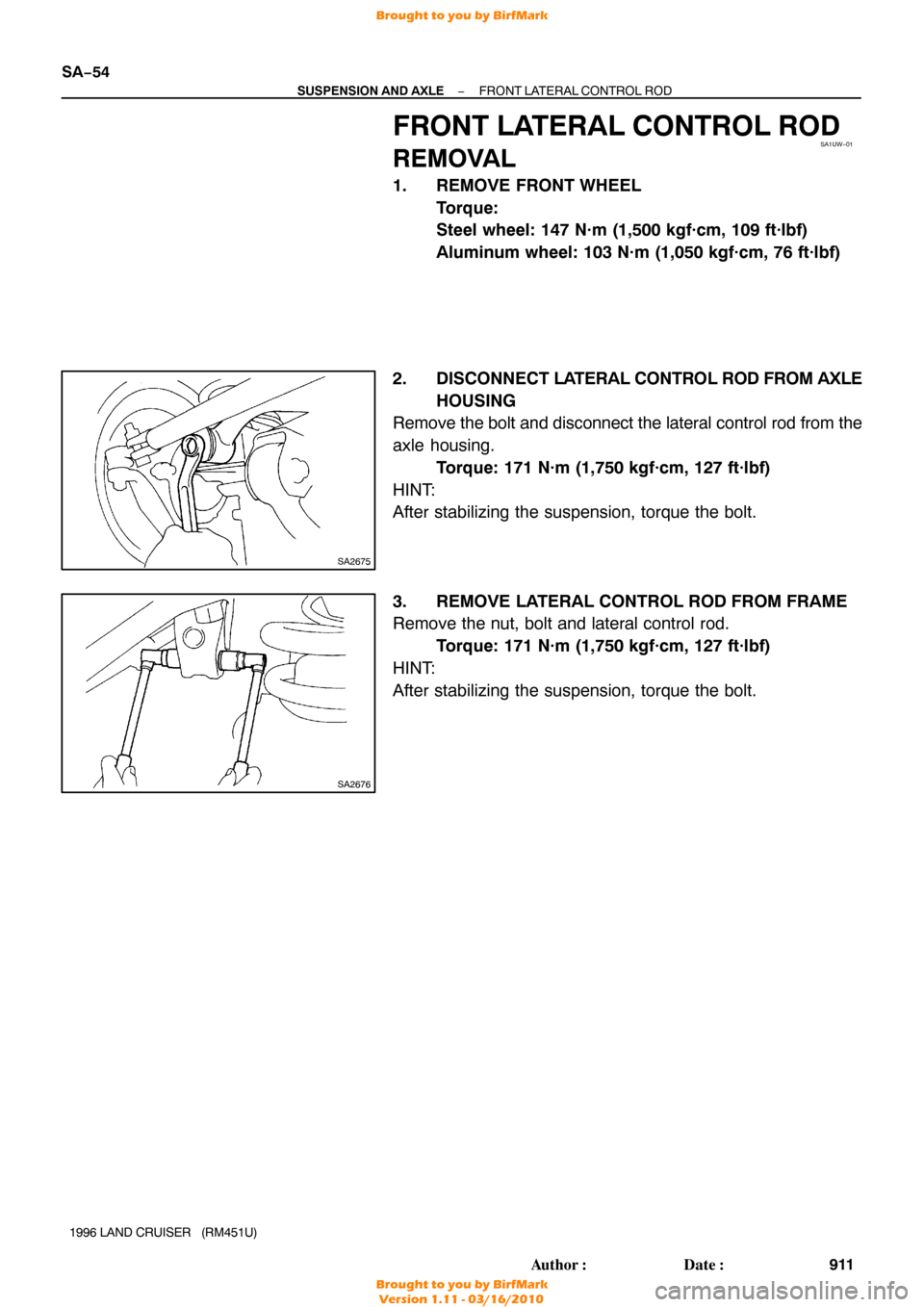
2. DISCONNECT LA TERAL CONTROL ROD FROM AXLE
HOUSING
Remove the bolt and disconnect the lateral control rod from the
axle housing.
Torque: 171 N·m (1,750 kgf·cm, 127 ft·lbf)
HINT:
After stabilizing the suspension, torque the bolt.
3. REMOVE LATERAL CONTROL ROD FROM FRAME
Remove the nut, bolt and lateral control rod. Torque: 171 N·m (1,750 kgf·cm, 127 ft·lbf)
HINT:
After stabilizing the suspension, torque the bolt.
Brought to you by BirfMark
Brought to you by BirfMark
Version 1.11 - 03/16/2010
Page 1120 of 1399
SA1UZ−01
SA2677
SA2678
−
SUSPENSION AND AXLE FRONT LEADING ARM
SA−57
914
Author�: Date�:
1996 LAND CRUISER (RM451U)
FRONT LEADING ARM
REMOVAL
1. REMOVE FRONT WHEEL
Torque:
Steel wheel: 147 N·m (1,500 kgf·cm, 109 ft·lbf)
Aluminum wheel: 103 N·m (1,050 kgf·cm, 76 ft·lbf)
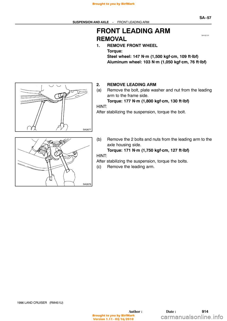
2. REMOVE LEADING ARM
(a) Remove the bolt, plate washer and nut from the leading arm to the frame side.
Torque: 177 N·m (1,800 kgf·cm, 130 ft·lbf)
HINT:
After stabilizing the suspension, torque the bolt.
(b) Remove the 2 bolts and nuts from the leading arm to the axle housing side.
Torque: 171 N·m (1,750 kgf·cm, 127 ft·lbf)
HINT:
After stabilizing the suspension, torque the bolts.
(c) Remove the leading arm.
Brought to you by BirfMark
Brought to you by BirfMark
Version 1.11 - 03/16/2010
Page 1123 of 1399
SA1V2−01
R07756
R08394
R13153
Paint
SA−60
−
SUSPENSION AND AXLE FRONT STABILIZER BAR
917
Author�: Date�:
1996 LAND CRUISER (RM451U)
FRONT STABILIZER BAR
REMOVAL
1. REMOVE FRONT WHEEL
Torque:
Steel wheel: 147 N·m (1,500 kgf·cm, 109 ft·lbf)
Aluminum wheel: 103 N·m (1,050 kgf·cm, 76 ft·lbf)
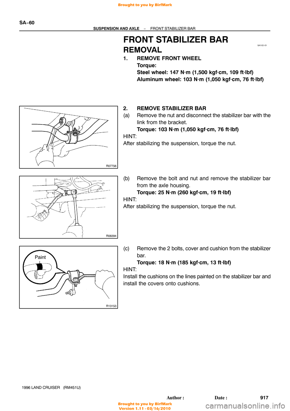
2. REMOVE STABILIZER BAR
(a) Remove the nut and disconnect the stabilizer bar with the
link from the bracket.
Torque: 103 N·m (1,050 kgf·cm, 76 ft·lbf)
HINT:
After stabilizing the suspension, torque the nut.
(b) Remove the bolt and nut and remove the stabilizer bar from the axle housing.
Torque: 25 N·m (260 kgf·cm, 19 ft·lbf)
HINT:
After stabilizing the suspension, torque the nut.
(c) Remove the 2 bolts, cover and cushion from the stabilizer
bar.
Torque: 18 N·m (185 kgf·cm, 13 ft·lbf)
HINT:
Install the cushions on the lines painted on the stabilizer bar and
install the covers onto cushions.
Brought to you by BirfMark
Brought to you by BirfMark
Version 1.11 - 03/16/2010
Page 1126 of 1399
SA1V5−01
−
SUSPENSION AND AXLE REAR AXLE SHAFT
SA−63
1996 LAND CRUISER (RM451U)
REMOVAL
REMOVE REAR AXLE SHAFT
(a) Remove the 6 set nuts and plate washers.
Torque: 34 N·m (340 kgf·cm, 25 ft·lbf)
(b) Using a brass bar and hammer, strike the center part of the axle shaft to remove the 6 cone washers.
(c) Install and gradually tighten 2 bolts evenly and pull the axle shaft.
(d) Remove the 2 bolts from the rear axle shaft.
(e) Remove the rear axle shaft and gasket.
NOTICE:
Be careful not to damage the oil seal.
Brought to you by BirfMark
Brought to you by BirfMark
Version 1.11 - 03/16/2010
Page 1130 of 1399
SA1V9−01
−
SUSPENSION AND AXLE REAR AXLE HUB
SA−67
1996 LAND CRUISER (RM451U)
REMOVAL
1. REMOVE REAR WHEEL
2. REMOVE REAR AXLE SHAFT (See page SA−63 )
3. REMOVE BRAKE CALIPER AND DISC (See page BR−34 )
4. DISCONNECT ABS SPEED SENSOR
Remove the bolt and disconnect the ABS speed sensor.
5. REMOVE REAR AXLE BEARING LOCK NUT
(a) Remove the 2 screws from the lock nut.
(b) Using SST, remove the lock nut. SST 09509−25011
6. REMOVE REAR AXLE HUB
(a) Pull out the axle hub, remove the lock nut plate and outer
bearing.
(b) Remove the axle hub.
Brought to you by BirfMark
Brought to you by BirfMark
Version 1.11 - 03/16/2010
Page 1133 of 1399
W00498
OK
−0.2 − 0.9 mm
SA−70
−
SUSPENSION AND AXLE REAR AXLE HUB
1996 LAND CRUISER (RM451U)
(g) Check the distance between top surface of axle housing
and the lock nut.
Standard distance:
−0.2 − 0.9 mm (−0.0079 − 0.0354 in.)
If the distance is greater than the specification, reassemble the
lock nut plate.
(h) Check that the hub with disc rotates smoothly and hub has no axial play.
5. INSTALL BEARING LOCK NUT SCREW
Tighten the 2 lock nut screws. Torque: 5.4 N·m (55 kgf·cm, 48 in.·lbf)
6. CONNECT ABS SPEED SENSOR
Connect the ABS speed sensor install the bolt.
Torque: 18 N·m (185 kgf·cm, 13 ft·lbf)
7. INSTALL BRAKE CALIPER (See page BR−38 )
8. INSTALL REAR AXLE SHAFT (See page SA−65 )
9. INSTALL REAR WHEEL Torque:
Steel wheel: 147 N·m (1,500 kgf·cm, 109 ft·lbf)
Aluminum wheel: 103 N·m (1,050 kgf·cm, 76 ft·lbf)
10. CHECK ABS SPEED SENSOR SIGNAL (See page DI−190 )
Brought to you by BirfMark
Brought to you by BirfMark
Version 1.11 - 03/16/2010
Page 1134 of 1399
SA1VC−01
−
SUSPENSION AND AXLE REAR WHEEL HUB BOLT
SA−71
928
Author�: Date�:
1996 LAND CRUISER (RM451U)
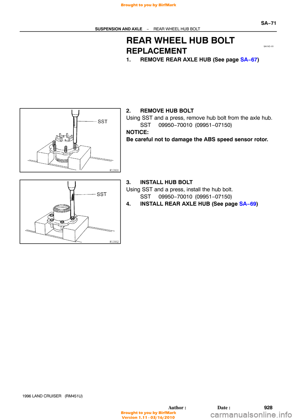
REAR WHEEL HUB BOLT
REPLACEMENT
1. REMOVE REAR AXLE HUB (See page SA−67 )
2. REMOVE HUB BOLT
Using SST and a press, remove hub bolt from the axle hub. SST 09950−70010 (09951 −07150)
NOTICE:
Be careful not to damage the ABS speed sensor rotor.
3. INSTALL HUB BOLT
Using SST and a press, install the hub bolt. SST 09950−70010 (09951 −07150)
4. INSTALL REAR AXLE HUB (See page SA−69 )
Brought to you by BirfMark
Brought to you by BirfMark
Version 1.11 - 03/16/2010

REMOVAL
REMOVE REAR AXLE SHAFT
(a) Remove the 6 set nuts and plate washers.
Torque: 34 N·m (340 kgf·cm, 25 ft")

REMOVAL
1. REMOVE REAR WHEEL
2. REMOVE REAR AXLE SHAFT (See page SA−63 )
3. REMOVE BRAKE CALIPER AND DISC (See")

(g) Check the distance between top surface of axle housing
and the lock nut.
Standard distance")