Page 1005 of 1399
PP2YQ−02
PP−64
−
PREPARATION SUPPLEMENTAL RESTRAINT SYSTEM
1996 LAND CRUISER (RM451U)
EQUIPMENT
Bolt
Length: 35 mm (1.38 in.)
Pitch: 1.0 mm (0.039 in.)
Diam: 6.0 mm (0.236 in.)Airbag disposal
Rope (no projections, difficult to break)Airbag disposal
Tire
Width: 185 mm (7.28 in.)
Inner diam: 360 mm (14.17 in.)Airbag disposal
Tire with disc wheel
Width: 185 mm (7.28 in.)
Inner diam: 360 mm (14.17 in.)Airbag disposal
Torque wrenchSteering wheel pad
Vinyl bagAirbag disposal
Brought to you by BirfMark
Brought to you by BirfMark
Version 1.11 - 03/16/2010
Page 1009 of 1399
PP2YV−01
PP−68
−
PREPARATION BODY
11 7
Author�: Date�:
1996 LAND CRUISER (RM451U)
BODY
SST (Special Service Tools)
09806−30010Windshield Moulding Remover
09812−00010Door Hinge Set Bolt Wrench
Brought to you by BirfMark
Brought to you by BirfMark
Version 1.11 - 03/16/2010
Page 1018 of 1399

PR06P−01
Z09285
Matchmarks
Transfer
Front Propeller Shaft
Z09286
Matchmarks
Transfer
Rear Propeller Shaft
−
PROPELLER SHAFT PROPELLER SHAFT ASSEMBLY
PR−3
1996 LAND CRUISER (RM451U)
REMOVAL
1. REMOVE FRONT PROPELLER SHAFT
(a) Place matchmarks on the propeller shaft flange and
transfer.
(b) Remove the 4 nuts and washers. Torque: 74 N·m (750 kgf·cm, 54 ft·lbf)
(c) Place matchmarks on the propeller shaft flange and dif-
ferential.
(d) Remove the 4 nuts, bolts and washers. Torque: 74 N·m (750 kgf·cm, 54 ft·lbf)
(e) Remove the front propeller shaft.
2. REMOVE REAR PROPELLER SHAFT
(a) Place matchmarks on the propeller shaft flange and
transfer.
(b) Remove the 4 nuts and washers. Torque: 88 N·m (900 kgf·cm, 65 ft·lbf)
(c) Place matchmarks on the propeller shaft flange and dif- ferential.
(d) Remove the 4 nuts, bolts and washers. Torque: 88 N·m (900 kgf·cm, 65 ft·lbf)
(e) Remove the rear propeller shaft.
Brought to you by BirfMark
Brought to you by BirfMark
Version 1.11 - 03/16/2010
Page 1039 of 1399

R05748
L
M
R05749
2 Times or more
R05751
−
SUPPLEMENTAL RESTRAINT SYSTEM STEERING WHEEL PAD AND SPIRAL CABLE
RS−15
1996 LAND CRUISER (RM451U)
(1) Install the 2 bolts with washers in the 2 bolt holes in
the steering wheel pad.
Bolt:
L: 35. mm (1.387 in.)
M: 6.0 mm (0.236 in.)
Pitch: 1.0 mm (0.039 in.)
NOTICE:
�Tighten the bolts by hand until the bolts become diffi-
cult to turn.
�Do not tighten the bolts too much.
(2) Using 3 wire harnesses, wind the wire harness at least 2 times each around the bolts installed on the
left and right sides of the steering wheel pad.
CAUTION:
�Tightly wind the wire harness around the bolts so that
there is no slack.
�If there is slack in the wire harness, the steering wheel
pad may come loose due to the shock when the air-
bag is deployed. This is highly dangerous.
(3) Face the upper surface of the steering wheel pad
upward. Separately tie the left and right sides of the
steering wheel pad to the disc wheel through the
hub nut holes. Position the steering wheel pad con-
nector so that it hangs downward through a hub
hole in the disc wheel.
CAUTION:
�Make sure that the wire harness is tight. It is very dan-
gerous when looseness in the wire harness results in
the steering wheel pad coming free through the shock
from the airbag deploying.
�Always tie down the steering wheel pad with the pad
side facing upward. It is very dangerous if the steer-
ing wheel pad is tied down with the metal surface fac-
ing upward as the wire harness will be cut by the
shock from the airbag deploying and the steering
wheel pad will be thrown into the air.
NOTICE:
The disc wheel will be marked by airbag deployment, so
when disposing of the airbag use a redundant disc wheel.
Brought to you by BirfMark
Brought to you by BirfMark
Version 1.11 - 03/16/2010
Page 1046 of 1399

RS0P8−01
RS−22
−
SUPPLEMENTAL RESTRAINT SYSTEM FRONT PASSENGER AIRBAG ASSEMBLY
1996 LAND CRUISER (RM451U)
REMOVAL
NOTICE:
If the wiring connector of the SRS is disconnected with the
ignition switch at ON or ACC, DTCs will be recorded.
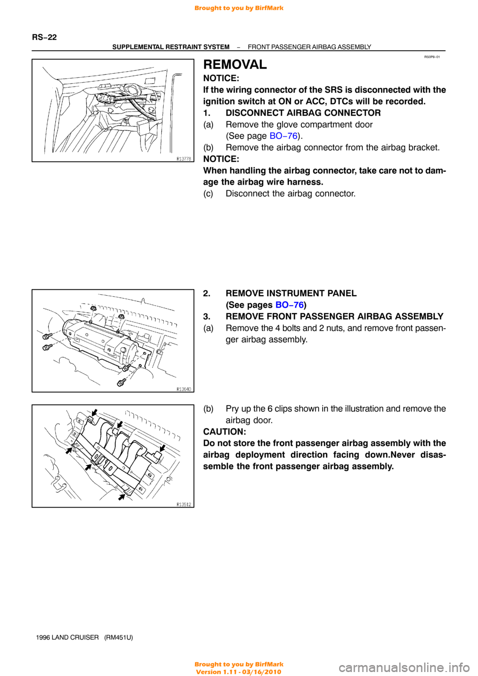
1. DISCONNECT AIRBAG CONNECTOR
(a) Remove the glove compartment door (See page BO−76 ).
(b) Remove the airbag connector from the airbag bracket.
NOTICE:
When handling the airbag connector , take care not to dam-
age the airbag wire harness.
(c) Disconnect the airbag connector.
2. REMOVE INSTRUMENT PANEL
(See pages BO−76 )
3. REMOVE FRONT PASSENGER AIRBAG ASSEMBLY
(a) Remove the 4 bolts and 2 nuts, and remove front passen-
ger airbag assembly.
(b) Pry up the 6 clips shown in the illustration and remove the airbag door.
CAUTION:
Do not store the front passenger airbag assembly with the
airbag deployment direction facing down.Never disas-
semble the front passenger airbag assembly.
Brought to you by BirfMark
Brought to you by BirfMark
Version 1.11 - 03/16/2010
Page 1055 of 1399

RS0PC−03
−
SUPPLEMENTAL RESTRAINT SYSTEM FRONT PASSENGER AIRBAG ASSEMBLY
RS−31
1996 LAND CRUISER (RM451U)
INSTALLATION
NOTICE:
Never use airbag parts from another vehicle. When replac-
ing parts, replace with new parts.
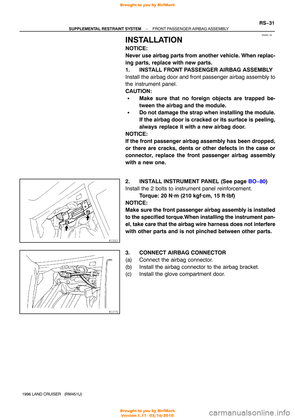
1. INSTALL FRONT PASSENGER AIRBAG ASSEMBLY
Install the airbag door and front passenger airbag assembly to
the instrument panel.
CAUTION:
�Make sure that no foreign objects are trapped be-
tween the airbag and the module.
�Do not damage the strap when installing the module.
If the airbag door is cracked or its surface is peeling,
always replace it with a new airbag door.
NOTICE:
If the front passenger airbag assembly has been dropped,
or there are cracks, dents or other defects in the case or
connector, replace the front passenger airbag assembly
with a new one.
2. INSTALL INSTRUMENT PANEL (See page BO−80)
Install the 2 bolts to instrument panel reinforcement. Torque: 20 N·m (210 kgf·cm, 15 ft·lbf)
NOTICE:
Make sure the front passenger airbag assembly is installed
to the specified torque.When installing the instrument pan-
el, take care that the airbag wire harness does not interfere
with other parts and is not pinched between other parts.
3. CONNECT AIRBAG CONNECTOR
(a) Connect the airbag connector.
(b) Install the airbag connector to the airbag bracket.
(c) Install the glove compartment door.
Brought to you by BirfMark
Brought to you by BirfMark
Version 1.11 - 03/16/2010
Page 1067 of 1399

SA1U9−02
Z03382
SA3213
AB
D
C
Front
R05628
A
B
A = B
SA−4
−
SUSPENSION AND AXLE FRONT WHEEL ALIGNMENT
861
Author�: Date�:
1996 LAND CRUISER (RM451U)
FRONT WHEEL ALIGNMENT
INSPECTION
1. MEASURE VEHICLE HEIGHT
Clearance:
A (Follow spring clearance): 36 mm (1.42 in.)
B (Bumper stopper clearance): 104 mm (4.09 in.)
If the clearance of the vehicle is not standard, try to level the ve-
hicle by rocking it down.
If still not correct, check for bad springs or suspension parts.
2. INSTALL CAMBER−CASTER−KINGPIN GAUGE OR ONTO WHEEL ALIGNMENT TESTER
Follow the specific instructions of the equipment manufacturer.
3. INSPECT CAMBER, CASTER AND STEERING AXIS INCLINATION
Camber
Left−right error1°00’ ± 45
45’ or less
Caster Left−right error3°00’ ± 1°
45’ or less
Steering axis inclination13 °00’ ± 45’
Camber, caster and steering axis inclination are not adjustable.
If measurements are not within the specification, inspect the
suspension parts for damaged and/or worn out parts and re-
place them as necessary.
4. INSPECT TOE −IN
To e−in
(total)A+B: 0.2 ° ± 0.2°
C −D: 2 ± 2 mm (0.08 ± 0.08 in.)
If toe− in is not within the specification, adjust by the tie rod end.
5. ADJUST TOE−IN
(a) Loosen the clamp bolts and nuts.
(b) Adjust toe−in to the correct value by turning the tie rod.
HINT:
Make sure that the lengths of the left and right tie rod ends are
the same.
(c) Torque the clamp bolts and nuts. Torque: 37 N·m (375 kgf·cm, 27 ft·lbf)
Brought to you by BirfMark
Brought to you by BirfMark
Version 1.11 - 03/16/2010
Page 1068 of 1399

R05626
Front
Side+10
° +60
°
−10 °
FA0507
FA0018
A B
Front BA
A: Inside
B: Outside
−
SUSPENSION AND AXLE FRONT WHEEL ALIGNMENT
SA−5
862
Author�: Date�:
1996 LAND CRUISER (RM451U)
HINT:
The clamps opening must be positioned at the rear of the tie rod
end face within 60 °±10° from the vehicle axis.
6. INSPECT WHEEL ANGLE
(a) Remove the caps of the knuckle stopper bolts and check the steering angles.
(b) Turn the steering wheel fully, and measure the turning angle.
Inside wheel32°00’ − 35°00’
Outside wheel31 °00’ (Reference)
HINT:
When the steering wheel is fully turned, make sure that the
wheel is not touching the body or brake flexible hose.
If maximum steering angles differ from the standard value, ad-
just the wheel angle with the knuckle stopper bolts.
Torque: 44 N·m (450 kgf·cm, 33 ft·lbf)
If the wheel angle still cannot be adjusted within limits, inspect
and replace damaged or worn steering parts.
Brought to you by BirfMark
Brought to you by BirfMark
Version 1.11 - 03/16/2010