Page 868 of 1399
EM1Q8−01
−
ENGINE MECHANICAL CYLINDER BLOCK
EM−83
1996 LAND CRUISER (RM451U)
DISASSEMBLY
1. REMOVE DRIVE PLATE
Uniformly loosen and remove the drive plate bolts, in several
passes, in the sequence shown.
2. INSTALL ENGINE TO ENGINE STAND FOR DIS-
ASSEMBLY
3. REMOVE CYLINDER HEAD (See page EM−28 )
4. REMOVE TIMING CHAIN AND GEARS (See page EM−13 )
5. REMOVE OIL FILTER (See page LU−2)
6. REMOVE OIL FILTER UNION
7. REMOVE KNOCK SENSORS
Using SST, remove the 2 knock sensors. SST 09816−30010
8. REMOVE PS PUMP
(a) Remove the 2 nuts and pump.
(b) Remove the O−ring from the pump.
Brought to you by BirfMark
Brought to you by BirfMark
Version 1.11 - 03/16/2010
Page 869 of 1399
EM−84
−
ENGINE MECHANICAL CYLINDER BLOCK
1996 LAND CRUISER (RM451U)
9. REMOVE RH ENGINE MOUNTING BRACKET
(a) Remove the nut and insulator.
(b) Remove the 4 bolts and bracket.
10. REMOVE LH ENGINE MOUNTING BRACKET
(a) Remove the nut and insulator.
(b) Remove the 4 bolts and bracket.
11. REMOVE OIL COOLER COVER AND OIL COOLER
Remove the 10 bolts, 2 nuts, oil cooler cover with the oil cooler
and gasket.
12. REMOVE REAR OIL SEAL RETAINER
Remove the 4 bolts and retainer.
13. CHECK CONNECTING ROD THRUST CLEARANCE
Using a dial indicator, measure the thrust clearance while mov-
ing the connecting rod back and forth.
Standard thrust clearance:
0.160 − 0.262 mm (0.0063 − 0.0103 in.)
Maximum thrust clearance: 0.362 mm (0.0143 in.)
If the thrust clearance is greater than maximum, replace the
connecting rod assembly. If necessary , replace the crankshaft.
Brought to you by BirfMark
Brought to you by BirfMark
Version 1.11 - 03/16/2010
Page 870 of 1399
−
ENGINE MECHANICAL CYLINDER BLOCK
EM−85
1996 LAND CRUISER (RM451U)
14. REMOVE CONNECTING ROD CAPS AND CHECK OIL
CLEARANCE
(a) Check the matchmarks on the connecting rod cap and
connecting rod to ensure correct reassembly.
(b) Remove the connecting rod cap nuts.
(c) Using a plastic− faced hammer, lightly tap the connecting
rod bolts and lift off the connecting rod cap.
HINT:
Keep the lower bearing inserted with the connecting rod cap.
(d) Cover the connecting rod bolts with a short piece of hose to protect the crankshaft from damage.
(e) Clean the crank pin and bearing.
(f) Check the crank pin and bearing for pitting and scratches.
If the crank pin or bearing is damaged, replace the bearings. If
necessary, grind or replace the crankshaft.
(g) Lay a strip of Plastigage across the crank pin.
Brought to you by BirfMark
Brought to you by BirfMark
Version 1.11 - 03/16/2010
Page 872 of 1399
P04620
−
ENGINE MECHANICAL CYLINDER BLOCK
EM−87
1996 LAND CRUISER (RM451U)
Standard sized bearing center wall thickness:
Mark ”2”1.744 − 1.747 mm (0.0687 − 0.0688 in.)
Mark ”3”1.747 − 1.750 mm (0.0688 − 0.0689 in.)
Mark ”4”1.750 − 1.753 mm (0.0689 − 0.0690 in.)
Mark ”5”1.753 − 1.756 mm (0.0690 − 0.0691 in.)
Mark ”6”1.756 − 1.759 mm (0.0691 − 0.0693 in.)
(k) Completely remove the Plastigage.
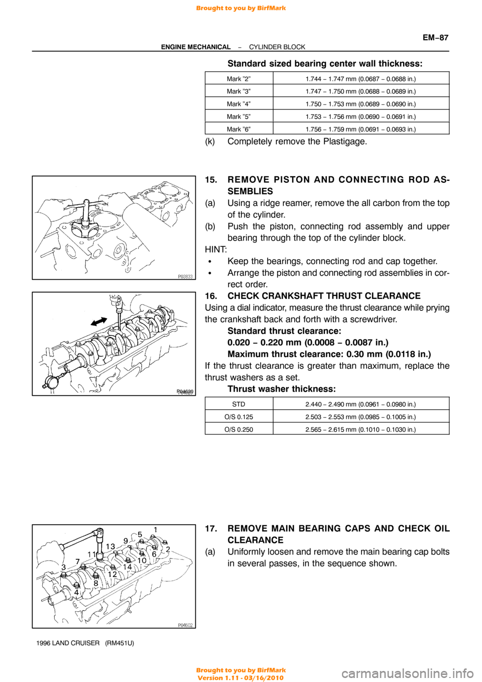
15. R E M O V E P I S TO N A N D C O N N E C T I N G R O D A S-
SEMBLIES
(a) Using a ridge reamer, remove the all carbon from the top of the cylinder.
(b) Push the piston, connecting rod assembly and upper bearing through the top of the cylinder block.
HINT:
�Keep the bearings, connecting rod and cap together.
�Arrange the piston and connecting rod assemblies in cor-
rect order.
16. CHECK CRANKSHAFT THRUST CLEARANCE
Using a dial indicator, measure the thrust clearance while prying
the crankshaft back and forth with a screwdriver. Standard thrust clearance:
0.020 − 0.220 mm (0.0008 − 0.0087 in.)
Maximum thrust clearance: 0.30 mm (0.0118 in.)
If the thrust clearance is greater than maximum, replace the
thrust washers as a set. Thrust washer thickness:
STD2.440 − 2.490 mm (0.0961 − 0.0980 in.)
O/S 0.1252.503 − 2.553 mm (0.0985 − 0.1005 in.)
O/S 0.2502.565 − 2.615 mm (0.1010 − 0.1030 in.)
17. REMOVE MAIN BEARING CAPS AND CHECK OIL
CLEARANCE
(a) Uniformly loosen and remove the main bearing cap bolts
in several passes, in the sequence shown.
Brought to you by BirfMark
Brought to you by BirfMark
Version 1.11 - 03/16/2010
Page 873 of 1399
EM−88
−
ENGINE MECHANICAL CYLINDER BLOCK
1996 LAND CRUISER (RM451U)
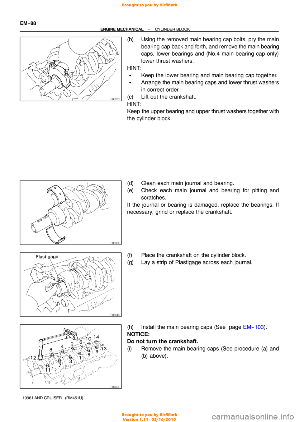
(b) Using the removed main bearing cap bolts, pry the main
bearing cap back and forth, and remove the main bearing
caps, lower bearings and (No.4 main bearing cap only)
lower thrust washers.
HINT:
�Keep the lower bearing and main bearing cap together.
�Arrange the main bearing caps and lower thrust washers
in correct order.
(c) Lift out the crankshaft.
HINT:
Keep the upper bearing and upper thrust washers together with
the cylinder block.
(d) Clean each main journal and bearing.
(e) Check each main journal and bearing for pitting and
scratches.
If the journal or bearing is damaged, replace the bearings. If
necessary, grind or replace the crankshaft.
(f) Place the crankshaft on the cylinder block.
(g) Lay a strip of Plastigage across each journal.
(h) Install the main bearing caps (See page EM−103).
NOTICE:
Do not turn the crankshaft.
(i) Remove the main bearing caps (See procedure (a) and (b) above).
Brought to you by BirfMark
Brought to you by BirfMark
Version 1.11 - 03/16/2010
Page 878 of 1399
−
ENGINE MECHANICAL CYLINDER BLOCK
EM−93
1996 LAND CRUISER (RM451U)
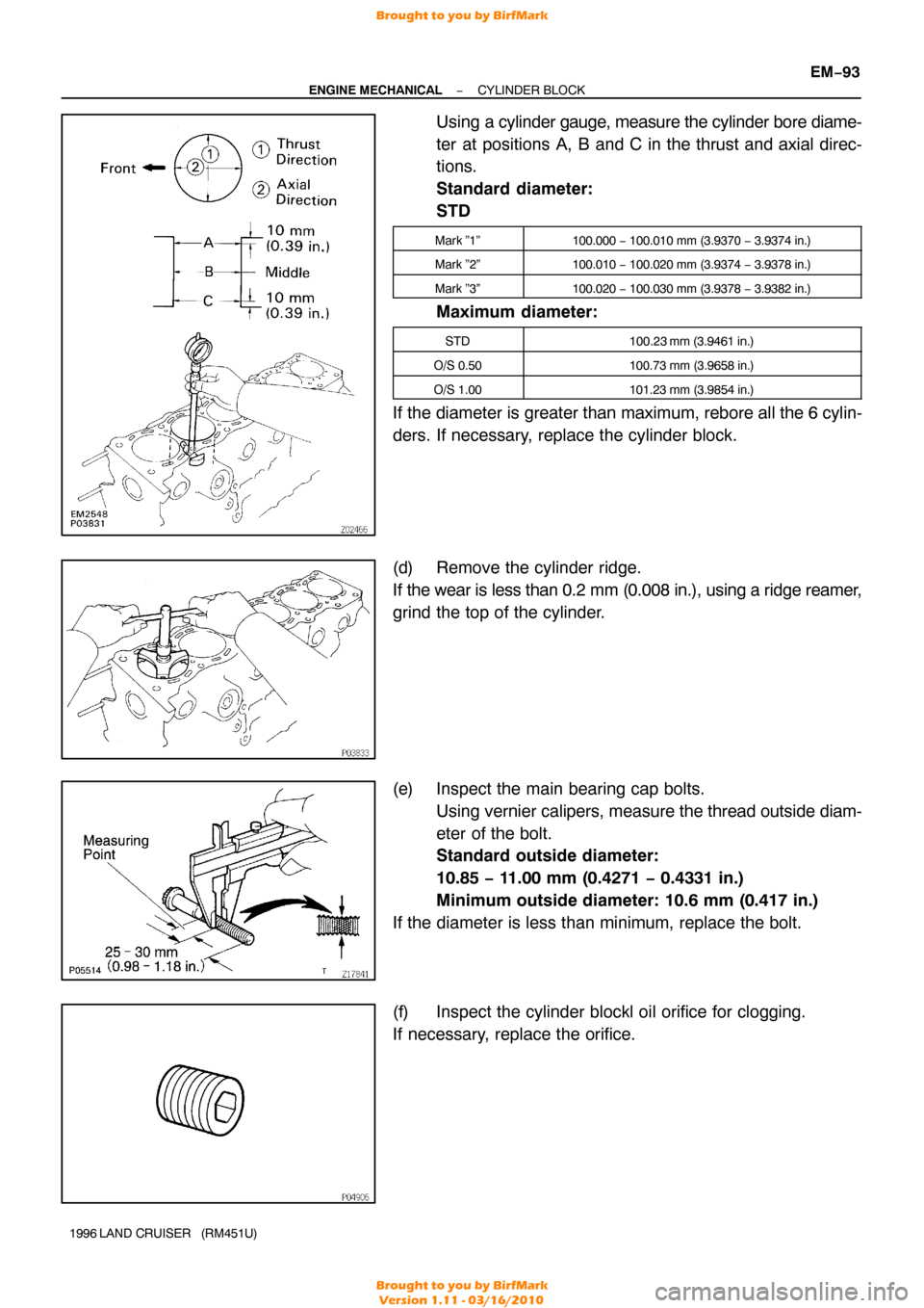
Using a cylinder gauge, measure the cylinder bore diame-
ter at positions A, B and C in the thrust and axial direc-
tions.
Standard diameter:
STD
Mark ”1”100.000 − 100.010 mm (3.9370 − 3.9374 in.)
Mark ”2”100.010 − 100.020 mm (3.9374 − 3.9378 in.)
Mark ”3”100.020 − 100.030 mm (3.9378 − 3.9382 in.)
Maximum diameter:
STD100.23 mm (3.9461 in.)
O/S 0.50100.73 mm (3.9658 in.)
O/S 1.00101.23 mm (3.9854 in.)
If the diameter is greater than maximum, rebore all the 6 cylin-
ders. If necessary, replace the cylinder block.
(d) Remove the cylinder ridge.
If the wear is less than 0.2 mm (0.008 in.), using a ridge reamer,
grind the top of the cylinder.
(e) Inspect the main bearing cap bolts.
Using vernier calipers, measure the thread outside diam-
eter of the bolt.
Standard outside diameter:
10.85 − 11.00 mm (0.4271 − 0.4331 in.)
Minimum outside diameter: 10.6 mm (0.417 in.)
If the diameter is less than minimum, replace the bolt.
(f) Inspect the cylinder blockl oil orifice for clogging.
If necessary, replace the orifice.
Brought to you by BirfMark
Brought to you by BirfMark
Version 1.11 - 03/16/2010
Page 882 of 1399
P03828
P03868
EM0227
−
ENGINE MECHANICAL CYLINDER BLOCK
EM−97
1996 LAND CRUISER (RM451U)
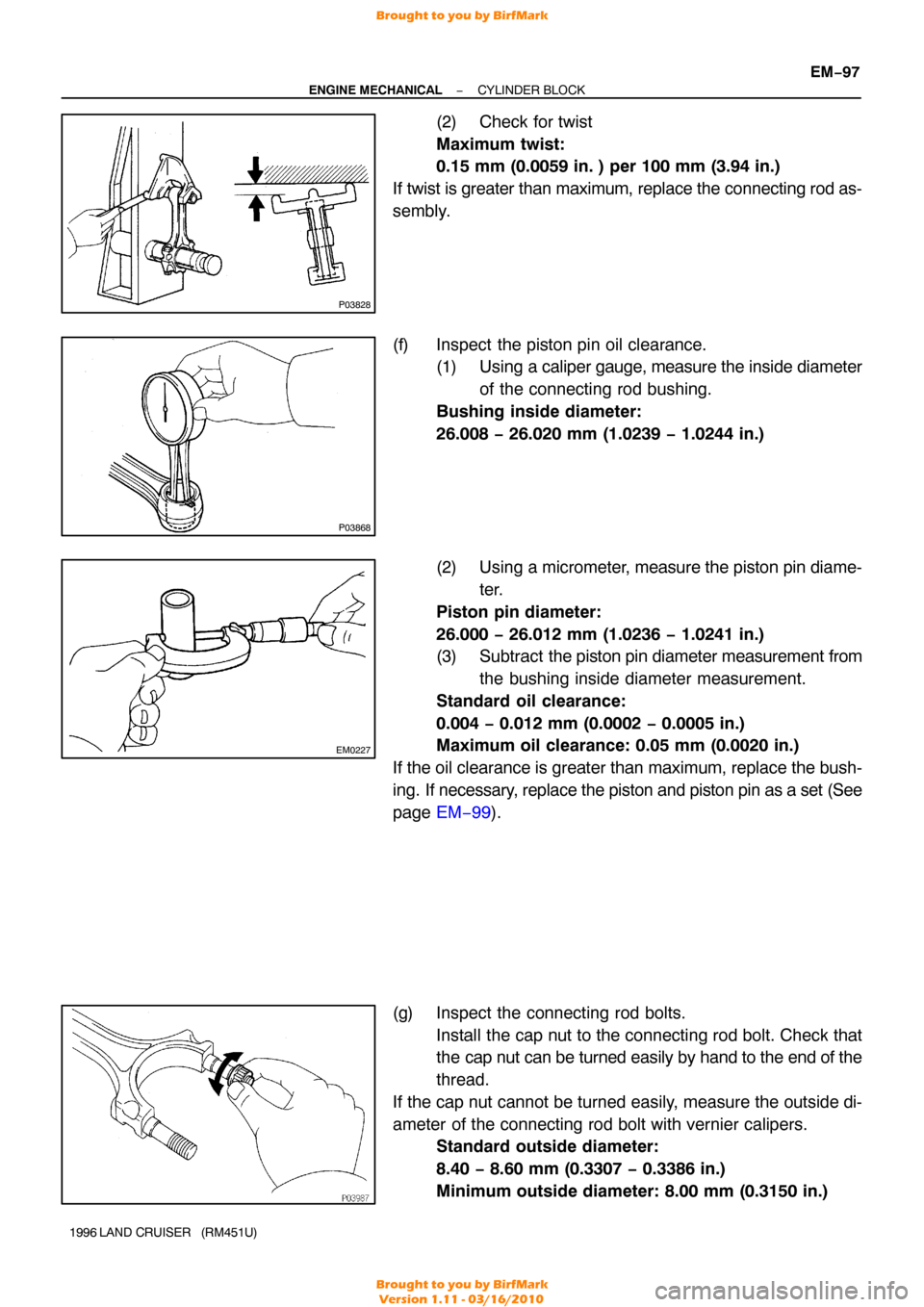
(2) Check for twist
Maximum twist:
0.15 mm (0.0059 in. ) per 100 mm (3.94 in.)
If twist is greater than maximum, replace the connecting rod as-
sembly.
(f) Inspect the piston pin oil clearance. (1) Using a caliper gauge, measure the inside diameter
of the connecting rod bushing.
Bushing inside diameter:
26.008 − 26.020 mm (1.0239 − 1.0244 in.)
(2) Using a micrometer, measure the piston pin diame-
ter.
Piston pin diameter:
26.000 − 26.012 mm (1.0236 − 1.0241 in.)
(3) Subtract the piston pin diameter measurement from
the bushing inside diameter measurement.
Standard oil clearance:
0.004 − 0.012 mm (0.0002 − 0.0005 in.)
Maximum oil clearance: 0.05 mm (0.0020 in.)
If the oil clearance is greater than maximum, replace the bush-
ing. If necessary, replace the piston and piston pin as a set (See
page EM−99 ).
(g) Inspect the connecting rod bolts. Install the cap nut to the connecting rod bolt. Check that
the cap nut can be turned easily by hand to the end of the
thread.
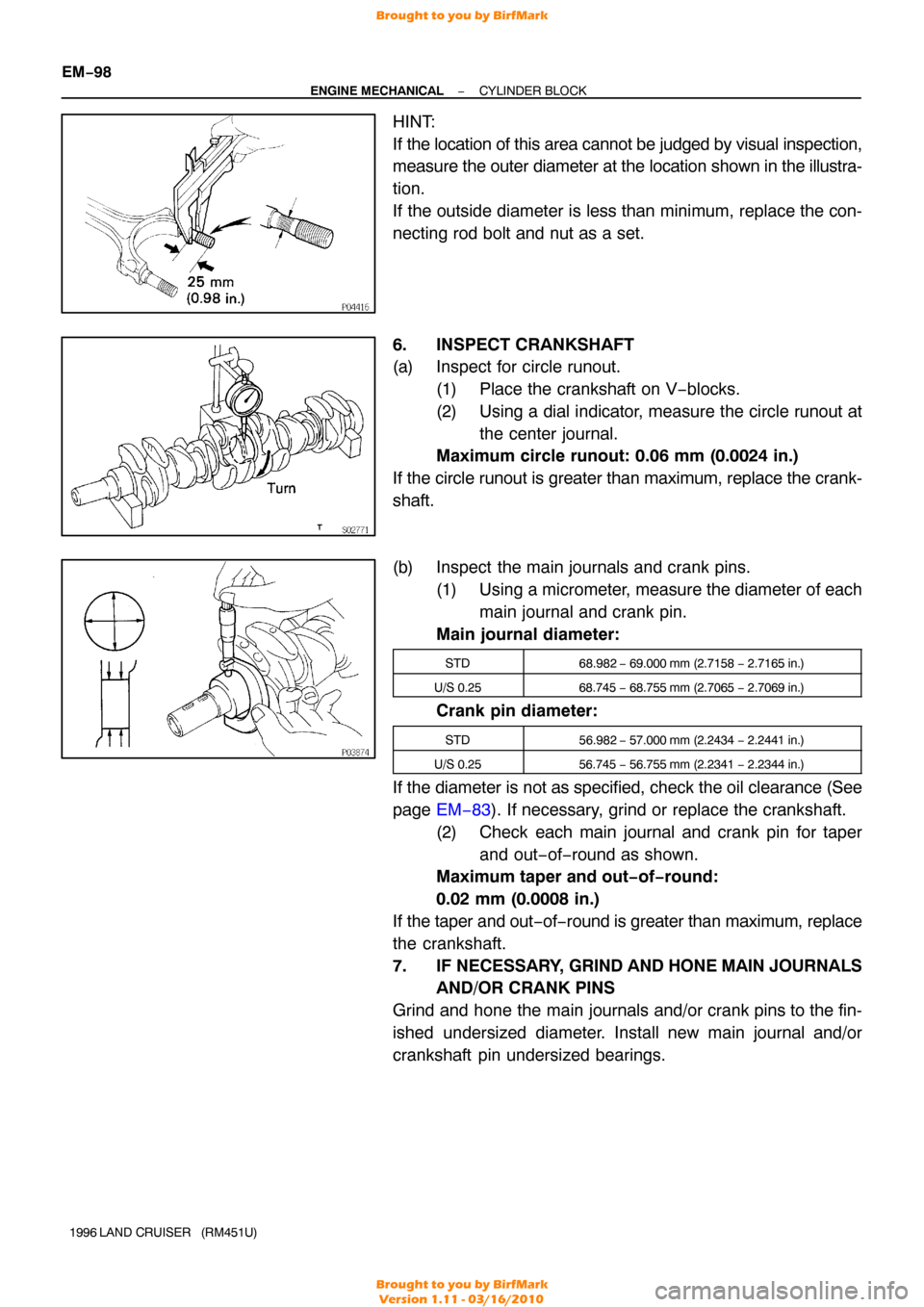
If the cap nut cannot be turned easily, measure the outside di-
ameter of the connecting rod bolt with vernier calipers. Standard outside diameter:
8.40 − 8.60 mm (0.3307 − 0.3386 in.)
Minimum outside diameter: 8.00 mm (0.3150 in.)
Brought to you by BirfMark
Brought to you by BirfMark
Version 1.11 - 03/16/2010
Page 883 of 1399
EM−98
−
ENGINE MECHANICAL CYLINDER BLOCK
1996 LAND CRUISER (RM451U)
HINT:
If the location of this area cannot be judged by visual inspection,
measure the outer diameter at the location shown in the illustra-
tion.
If the outside diameter is less than minimum, replace the con-
necting rod bolt and nut as a set.
6. INSPECT CRANKSHAFT
(a) Inspect for circle runout. (1) Place the crankshaft on V−blocks.
(2) Using a dial indicator, measure the circle runout atthe center journal.
Maximum circle runout: 0.06 mm (0.0024 in.)
If the circle runout is greater than maximum, replace the crank-
shaft.
(b) Inspect the main journals and crank pins. (1) Using a micrometer, measure the diameter of each
main journal and crank pin.
Main journal diameter:
STD68.982 − 69.000 mm (2.7158 − 2.7165 in.)
U/S 0.2568.745 − 68.755 mm (2.7065 − 2.7069 in.)
Crank pin diameter:
STD56.982 − 57.000 mm (2.2434 − 2.2441 in.)
U/S 0.2556.745 − 56.755 mm (2.2341 − 2.2344 in.)
If the diameter is not as specified, check the oil clearance (See
page EM−83 ). If necessary, grind or replace the crankshaft.
(2) Check each main journal and crank pin for taper and out−of−round as shown.
Maximum taper and out−of−round:
0.02 mm (0.0008 in.)
If the taper and out −of− round is greater than maximum, replace
the crankshaft.
7. IF NECESSARY, GRIND AND HONE MAIN JOURNALS
AND/OR CRANK PINS
Grind and hone the main journals and/or crank pins to the fin-
ished undersized diameter. Install new main journal and/or
crankshaft pin undersized bearings.
Brought to you by BirfMark
Brought to you by BirfMark
Version 1.11 - 03/16/2010