Page 1067 of 1399

SA1U9−02
Z03382
SA3213
AB
D
C
Front
R05628
A
B
A = B
SA−4
−
SUSPENSION AND AXLE FRONT WHEEL ALIGNMENT
861
Author�: Date�:
1996 LAND CRUISER (RM451U)
FRONT WHEEL ALIGNMENT
INSPECTION
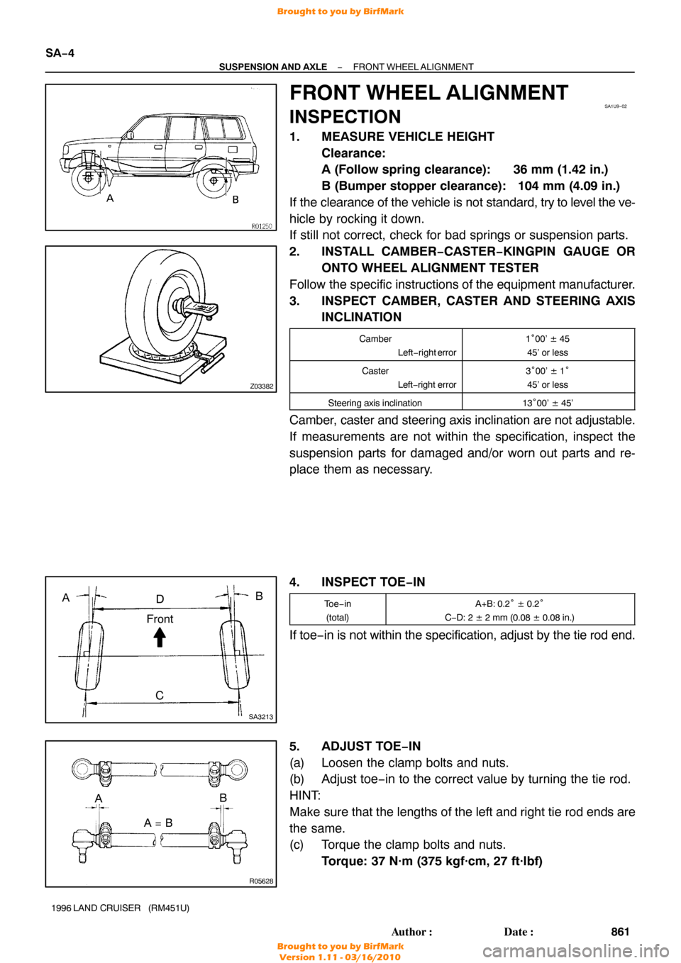
1. MEASURE VEHICLE HEIGHT
Clearance:
A (Follow spring clearance): 36 mm (1.42 in.)
B (Bumper stopper clearance): 104 mm (4.09 in.)
If the clearance of the vehicle is not standard, try to level the ve-
hicle by rocking it down.
If still not correct, check for bad springs or suspension parts.
2. INSTALL CAMBER−CASTER−KINGPIN GAUGE OR ONTO WHEEL ALIGNMENT TESTER
Follow the specific instructions of the equipment manufacturer.
3. INSPECT CAMBER, CASTER AND STEERING AXIS INCLINATION
Camber
Left−right error1°00’ ± 45
45’ or less
Caster Left−right error3°00’ ± 1°
45’ or less
Steering axis inclination13 °00’ ± 45’
Camber, caster and steering axis inclination are not adjustable.
If measurements are not within the specification, inspect the
suspension parts for damaged and/or worn out parts and re-
place them as necessary.
4. INSPECT TOE −IN
To e−in
(total)A+B: 0.2 ° ± 0.2°
C −D: 2 ± 2 mm (0.08 ± 0.08 in.)
If toe− in is not within the specification, adjust by the tie rod end.
5. ADJUST TOE−IN
(a) Loosen the clamp bolts and nuts.
(b) Adjust toe−in to the correct value by turning the tie rod.
HINT:
Make sure that the lengths of the left and right tie rod ends are
the same.
(c) Torque the clamp bolts and nuts. Torque: 37 N·m (375 kgf·cm, 27 ft·lbf)
Brought to you by BirfMark
Brought to you by BirfMark
Version 1.11 - 03/16/2010
Page 1068 of 1399

R05626
Front
Side+10
° +60
°
−10 °
FA0507
FA0018
A B
Front BA
A: Inside
B: Outside
−
SUSPENSION AND AXLE FRONT WHEEL ALIGNMENT
SA−5
862
Author�: Date�:
1996 LAND CRUISER (RM451U)
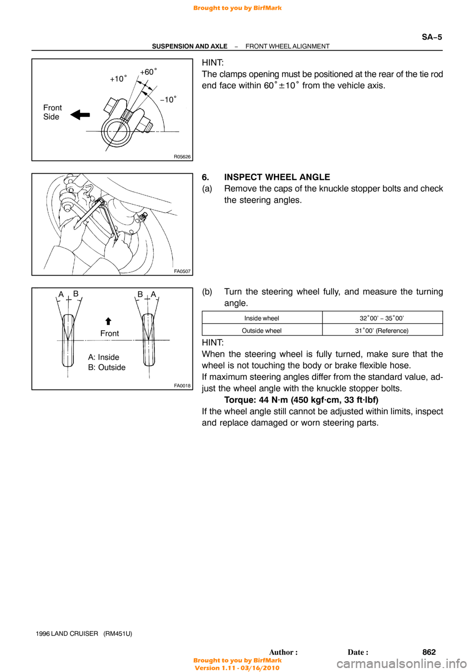
HINT:
The clamps opening must be positioned at the rear of the tie rod
end face within 60 °±10° from the vehicle axis.
6. INSPECT WHEEL ANGLE
(a) Remove the caps of the knuckle stopper bolts and check the steering angles.
(b) Turn the steering wheel fully, and measure the turning angle.
Inside wheel32°00’ − 35°00’
Outside wheel31 °00’ (Reference)
HINT:
When the steering wheel is fully turned, make sure that the
wheel is not touching the body or brake flexible hose.
If maximum steering angles differ from the standard value, ad-
just the wheel angle with the knuckle stopper bolts.
Torque: 44 N·m (450 kgf·cm, 33 ft·lbf)
If the wheel angle still cannot be adjusted within limits, inspect
and replace damaged or worn steering parts.
Brought to you by BirfMark
Brought to you by BirfMark
Version 1.11 - 03/16/2010
Page 1331 of 1399

SS1EC−02
SS−30
−
SERVICE SPECIFICATIONS SUSPENSION AND AXLE
153
Author�: Date�:
1996 LAND CRUISER (RM451U)
SUSPENSION AND AXLE
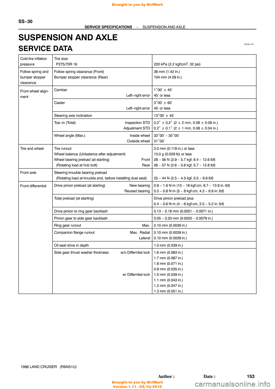
SERVICE DATA
Cold tire inflation
pressureTire size
P275/70R 16
220 kPa (2.2 kgf/cm2, 32 psi)
Follow spring and
bumper stopper
clearanceFollow spring clearance (Front)
Bumper stopper clearance (Rear)36 mm (1.42 in.)
104 mm (4.09 in.)
Front wheel align-
mentCamber Left−right error1°00’ ± 45’
45’ or less
Caster Left−right error3°00’ ± 60’
45’ or less
Steering axis inclination13 °00’ ± 45’
To e −in (Total) Inspection STD
Adjustment STD0.2 ° ± 0.2° (2 ± 2 mm, 0.08 ± 0.08 in.)
0.2 ° ± 0.1° (2 ± 1 mm, 0.08 ± 0.04 in.)
Wheel angle (Max.) Inside wheel
Outside wheel32 °00’ − 35°00’
31 °00’
Tire and wheelTire runout
Wheel balance (Unbalance after adjustment)
Wheel bearing preload (at starting) Front
(Rotating load at hub bolt) Rear3.0 mm (0.118 in.) or less
13.0 g (0.029 lb) or less
28 − 56 N (2.9 − 5.7 kgf, 6.4 − 12.6 lbf)
26 − 57 N (2.6 − 5.8 kgf, 5.7 − 12.8 lbf)
Front axleSteering knuckle bearing preload
(Rotating load at knuckle end, before installing dust seal)
25 − 44 N (2.5 − 4.5 kgf, 5.5 − 9.9 lbf)
Front dif ferentialDrive pinion preload (at starting) New bearing
Reused bearing0.9 − 1.6 N·m (10 − 16 kgf·cm, 8.7 − 13.9 in.·lbf)
0.5 − 0.8 N·m (5 − 8 kgf·cm, 4.3 − 6.9 in.·lbf)
Total preload (at starting)Drive pinion preload plus
0.4 − 0.6 N·m (4 − 6 kgf·cm, 3.5 − 5.2 in.·lbf)
Drive pinion to ring gear backlash0.13 − 0.18 mm (0.0051 − 0.0071 in.)
Pinion gear to side gear backlash0.05 − 0.20 mm (0.0020 − 0.0079 in.)
Ring gear runout Max.0.10 mm (0.0039 in.)
Companion flange runoutMax. Radial
Lateral0.10 mm (0.0039 in.)
0.10 mm (0.0039 in.)
Oil seal drive in depth1.0 mm (0.039 in.)
Side gear thrust washer thickness w/o Differntial lock
w/ Differntial lock1.6 mm (0.063 in.)
1.7 mm (0.067 in.)
1.8 mm (0.071 in.)
0.9 mm (0.035 in.)
1.0 mm (0.039 in.)
1.1 mm (0.043 in.)
1.2 mm (0.047 in.)
1.3 mm (0.051 in.)
Brought to you by BirfMark
Brought to you by BirfMark
Version 1.11 - 03/16/2010