Page 1407 of 2890
2) Connect compressor harness.
3) Connect alternator harness.
4) Install compressor V-belt (Rear).
After adjusting belt tension, tighten tension pulley lock nut
securely.
G4M0632
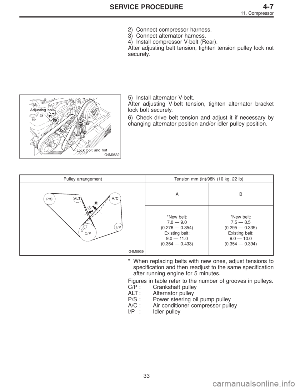
5) Install alternator V-belt.
After adjusting V-belt tension, tighten alternator bracket
lock bolt securely.
6) Check drive belt tension and adjust it if necessary by
changing alternator position and/or idler pulley position.
Pulley arrangement Tension mm (in)/98N (10 kg, 22 lb)
G4M0939
AB
*New belt:
7.0—9.0
(0.276—0.354)
Existing belt:
9.0—11.0
(0.354—0.433)*New belt:
7.5—8.5
(0.295—0.335)
Existing belt:
9.0—10.0
(0.354—0.394)
* When replacing belts with new ones, adjust tensions to
specification and then readjust to the same specification
after running engine for 5 minutes.
Figures in table refer to the number of grooves in pulleys.
C/P : Crankshaft pulley
ALT : Alternator pulley
P/S : Power steering oil pump pulley
A/C : Air conditioner compressor pulley
I/P : Idler pulley
33
4-7SERVICE PROCEDURE
11. Compressor
Page 1418 of 2890
1. Air Conditioning System Diagnosis
41
4-7DIAGNOSTICS
1. Air Conditioning System Diagnosis
Page 1419 of 2890
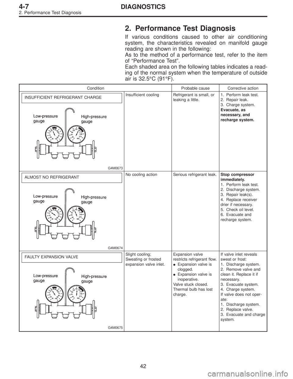
2. Performance Test Diagnosis
If various conditions caused to other air conditioning
system, the characteristics revealed on manifold gauge
reading are shown in the following:
As to the method of a performance test, refer to the item
of“Performance Test”.
Each shaded area on the following tables indicates a read-
ing of the normal system when the temperature of outside
air is 32.5°C (91°F).
Condition Probable cause Corrective action
INSUFFICIENT REFRIGERANT CHARGE
G4M0673
Insufficient cooling Refrigerant is small, or
leaking a little.1. Perform leak test.
2. Repair leak.
3. Charge system.
Evacuate, as
necessary, and
recharge system.
ALMOST NO REFRIGERANT
G4M0674
No cooling action Serious refrigerant leak.Stop compressor
immediately.
1. Perform leak test.
2. Discharge system.
3. Repair leak(s).
4. Replace receiver
drier if necessary.
5. Check oil level.
6. Evacuate and
recharge system.
FAULTY EXPANSION VALVE
G4M0675
Slight cooling;
Sweating or frosted
expansion valve inlet.Expansion valve
restricts refrigerant flow.
�Expansion valve is
clogged.
�Expansion valve is
inoperative.
Valve stuck closed.
Thermal bulb has lost
charge.If valve inlet reveals
sweat or frost:
1. Discharge system.
2. Remove valve and
clean it. Replace it if
necessary.
3. Evacuate system.
4. Charge system.
If valve does not oper-
ate:
1. Discharge system.
2. Replace valve.
3. Evacuate and charge
system.
42
4-7DIAGNOSTICS
2. Performance Test Diagnosis
Page 1420 of 2890
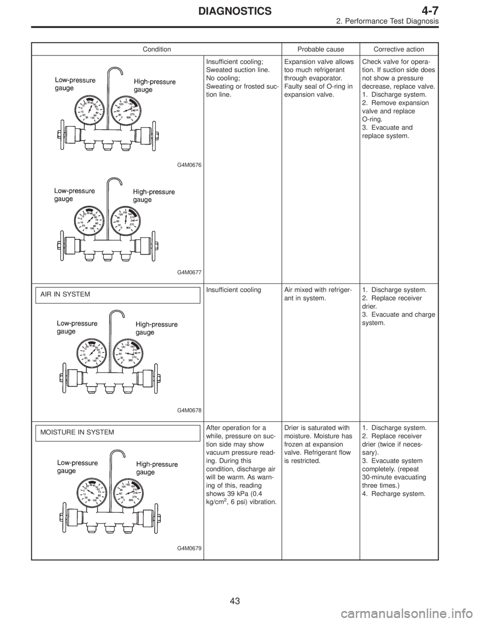
Condition Probable cause Corrective action
G4M0676
G4M0677
Insufficient cooling;
Sweated suction line.
No cooling;
Sweating or frosted suc-
tion line.Expansion valve allows
too much refrigerant
through evaporator.
Faulty seal of O-ring in
expansion valve.Check valve for opera-
tion. If suction side does
not show a pressure
decrease, replace valve.
1. Discharge system.
2. Remove expansion
valve and replace
O-ring.
3. Evacuate and
replace system.
AIR IN SYSTEM
G4M0678
Insufficient cooling Air mixed with refriger-
ant in system.1. Discharge system.
2. Replace receiver
drier.
3. Evacuate and charge
system.
MOISTURE IN SYSTEM
G4M0679
After operation for a
while, pressure on suc-
tion side may show
vacuum pressure read-
ing. During this
condition, discharge air
will be warm. As warn-
ing of this, reading
shows 39 kPa (0.4
kg/cm
2, 6 psi) vibration.Drier is saturated with
moisture. Moisture has
frozen at expansion
valve. Refrigerant flow
is restricted.1. Discharge system.
2. Replace receiver
drier (twice if neces-
sary).
3. Evacuate system
completely. (repeat
30-minute evacuating
three times.)
4. Recharge system.
43
4-7DIAGNOSTICS
2. Performance Test Diagnosis
Page 1421 of 2890
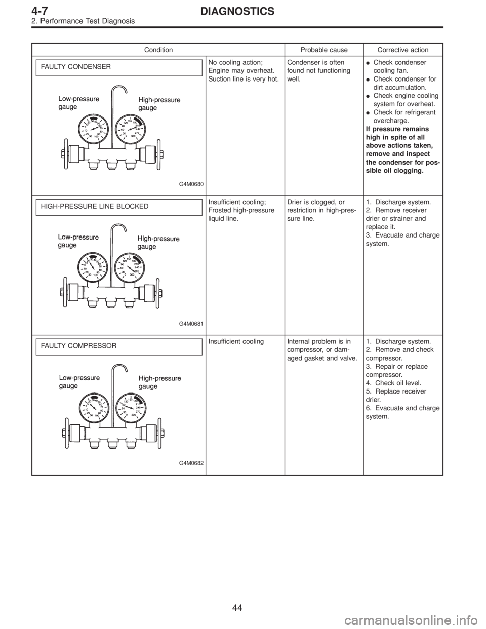
Condition Probable cause Corrective action
FAULTY CONDENSER
G4M0680
No cooling action;
Engine may overheat.
Suction line is very hot.Condenser is often
found not functioning
well.�Check condenser
cooling fan.
�Check condenser for
dirt accumulation.
�Check engine cooling
system for overheat.
�Check for refrigerant
overcharge.
If pressure remains
high in spite of all
above actions taken,
remove and inspect
the condenser for pos-
sible oil clogging.
HIGH-PRESSURE LINE BLOCKED
G4M0681
Insufficient cooling;
Frosted high-pressure
liquid line.Drier is clogged, or
restriction in high-pres-
sure line.1. Discharge system.
2. Remove receiver
drier or strainer and
replace it.
3. Evacuate and charge
system.
FAULTY COMPRESSOR
G4M0682
Insufficient cooling Internal problem is in
compressor, or dam-
aged gasket and valve.1. Discharge system.
2. Remove and check
compressor.
3. Repair or replace
compressor.
4. Check oil level.
5. Replace receiver
drier.
6. Evacuate and charge
system.
44
4-7DIAGNOSTICS
2. Performance Test Diagnosis
Page 1475 of 2890
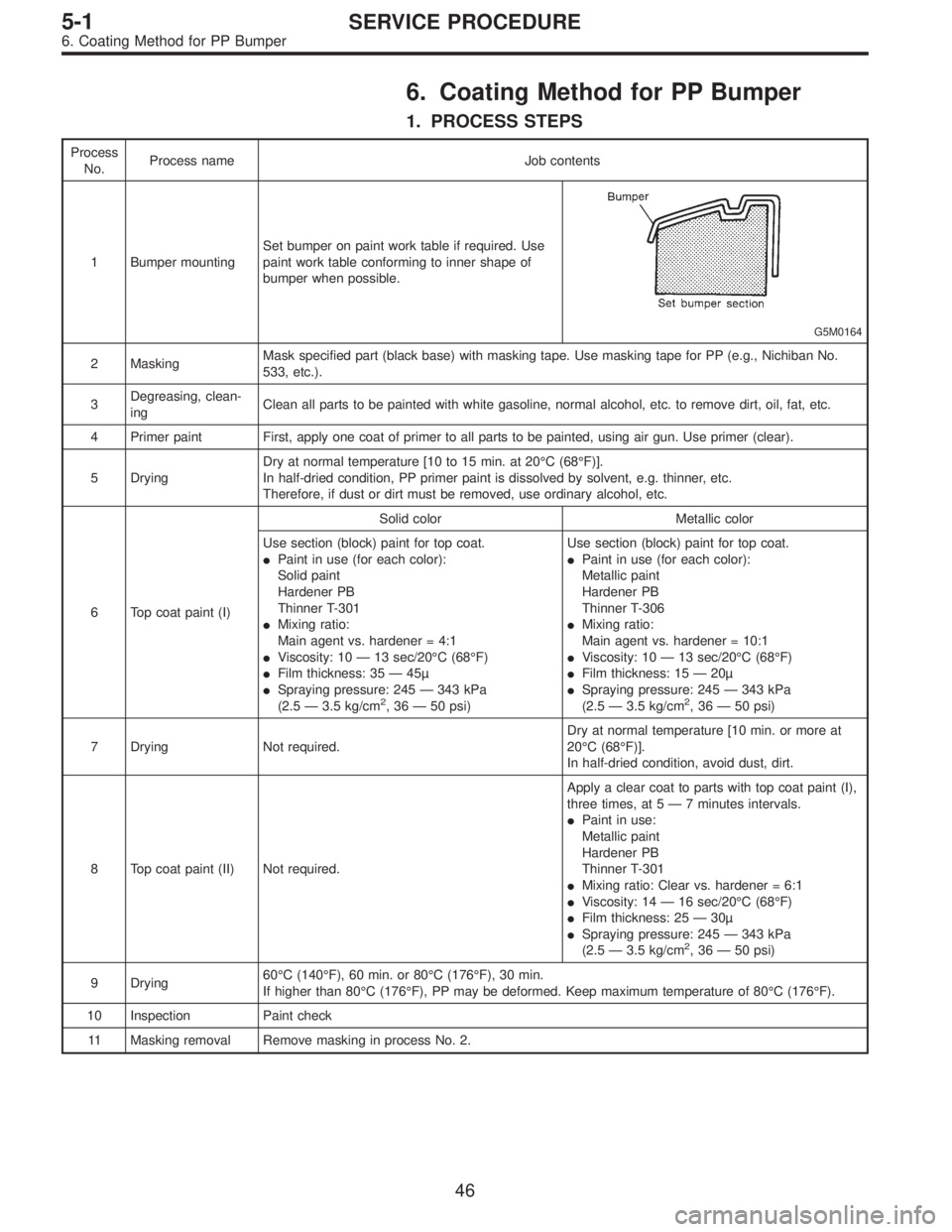
6. Coating Method for PP Bumper
1. PROCESS STEPS
Process
No.Process name Job contents
1 Bumper mountingSet bumper on paint work table if required. Use
paint work table conforming to inner shape of
bumper when possible.
G5M0164
2 MaskingMask specified part (black base) with masking tape. Use masking tape for PP (e.g., Nichiban No.
533, etc.).
3Degreasing, clean-
ingClean all parts to be painted with white gasoline, normal alcohol, etc. to remove dirt, oil, fat, etc.
4 Primer paint First, apply one coat of primer to all parts to be painted, using air gun. Use primer (clear).
5 DryingDry at normal temperature [10 to 15 min. at 20°C (68°F)].
In half-dried condition, PP primer paint is dissolved by solvent, e.g. thinner, etc.
Therefore, if dust or dirt must be removed, use ordinary alcohol, etc.
6 Top coat paint (I)Solid color Metallic color
Use section (block) paint for top coat.
�Paint in use (for each color):
Solid paint
Hardener PB
Thinner T-301
�Mixing ratio:
Main agent vs. hardener = 4:1
�Viscosity: 10—13 sec/20°C (68°F)
�Film thickness: 35—45µ
�Spraying pressure: 245—343 kPa
(2.5—3.5 kg/cm
2,36—50 psi)Use section (block) paint for top coat.
�Paint in use (for each color):
Metallic paint
Hardener PB
Thinner T-306
�Mixing ratio:
Main agent vs. hardener = 10:1
�Viscosity: 10—13 sec/20°C (68°F)
�Film thickness: 15—20µ
�Spraying pressure: 245—343 kPa
(2.5—3.5 kg/cm2,36—50 psi)
7 Drying Not required.Dry at normal temperature [10 min. or more at
20°C (68°F)].
In half-dried condition, avoid dust, dirt.
8 Top coat paint (II) Not required.Apply a clear coat to parts with top coat paint (I),
three times, at 5—7 minutes intervals.
�Paint in use:
Metallic paint
Hardener PB
Thinner T-301
�Mixing ratio: Clear vs. hardener = 6:1
�Viscosity: 14—16 sec/20°C (68°F)
�Film thickness: 25—30µ
�Spraying pressure: 245—343 kPa
(2.5—3.5 kg/cm
2,36—50 psi)
9 Drying60°C (140°F), 60 min. or 80°C (176°F), 30 min.
If higher than 80°C (176°F), PP may be deformed. Keep maximum temperature of 80°C (176°F).
10 Inspection Paint check
11 Masking removal Remove masking in process No. 2.
46
5-1SERVICE PROCEDURE
6. Coating Method for PP Bumper
Page 1476 of 2890
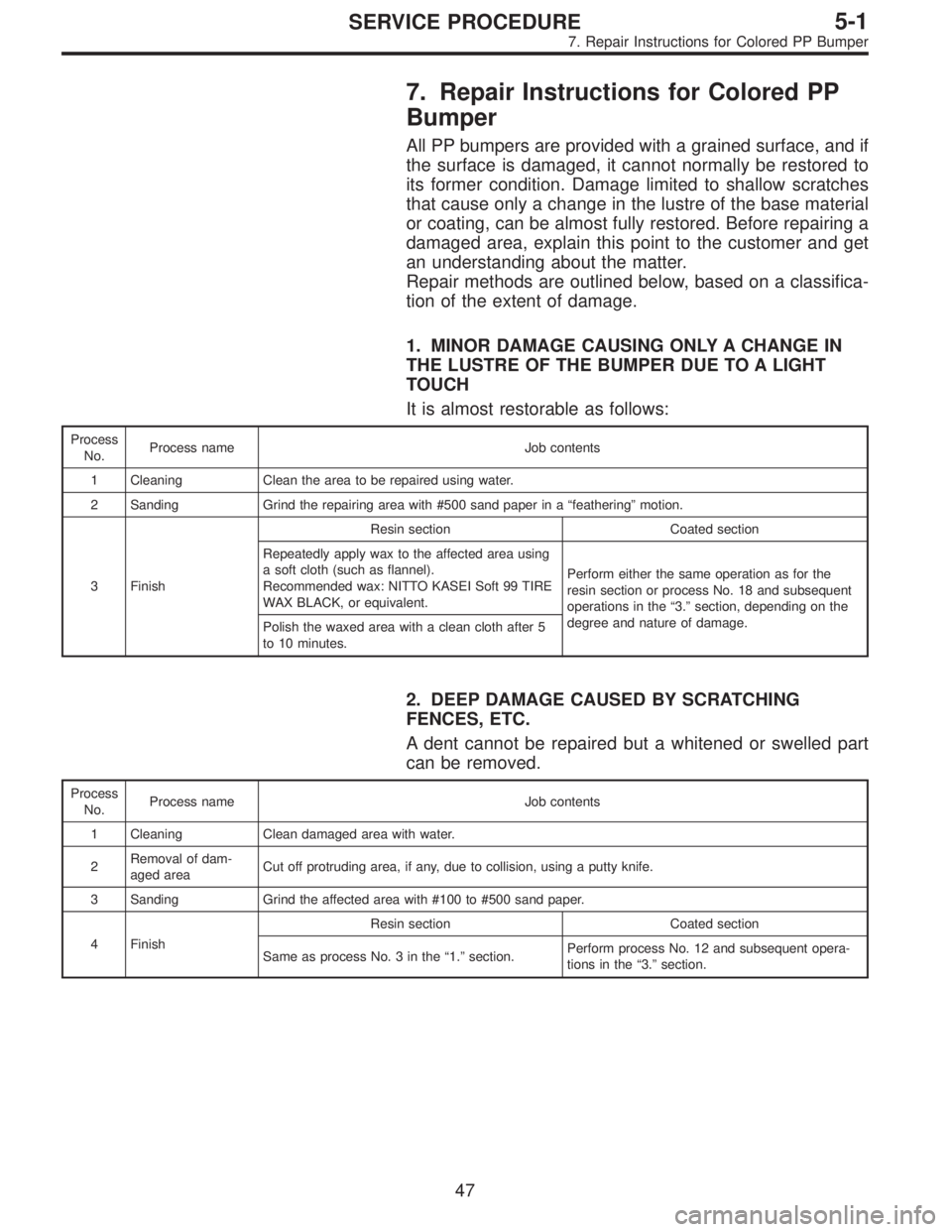
7. Repair Instructions for Colored PP
Bumper
All PP bumpers are provided with a grained surface, and if
the surface is damaged, it cannot normally be restored to
its former condition. Damage limited to shallow scratches
that cause only a change in the lustre of the base material
or coating, can be almost fully restored. Before repairing a
damaged area, explain this point to the customer and get
an understanding about the matter.
Repair methods are outlined below, based on a classifica-
tion of the extent of damage.
1. MINOR DAMAGE CAUSING ONLY A CHANGE IN
THE LUSTRE OF THE BUMPER DUE TO A LIGHT
TOUCH
It is almost restorable as follows:
Process
No.Process name Job contents
1 Cleaning Clean the area to be repaired using water.
2 Sanding Grind the repairing area with #500 sand paper in a“feathering”motion.
3 FinishResin section Coated section
Repeatedly apply wax to the affected area using
a soft cloth (such as flannel).
Recommended wax: NITTO KASEI Soft 99 TIRE
WAX BLACK, or equivalent.Perform either the same operation as for the
resin section or process No. 18 and subsequent
operations in the“3.”section, depending on the
degree and nature of damage.
Polish the waxed area with a clean cloth after 5
to 10 minutes.
2. DEEP DAMAGE CAUSED BY SCRATCHING
FENCES, ETC.
A dent cannot be repaired but a whitened or swelled part
can be removed.
Process
No.Process name Job contents
1 Cleaning Clean damaged area with water.
2Removal of dam-
aged areaCut off protruding area, if any, due to collision, using a putty knife.
3 Sanding Grind the affected area with #100 to #500 sand paper.
4 FinishResin section Coated section
Same as process No. 3 in the“1.”section.Perform process No. 12 and subsequent opera-
tions in the“3.”section.
47
5-1SERVICE PROCEDURE
7. Repair Instructions for Colored PP Bumper
Page 1479 of 2890
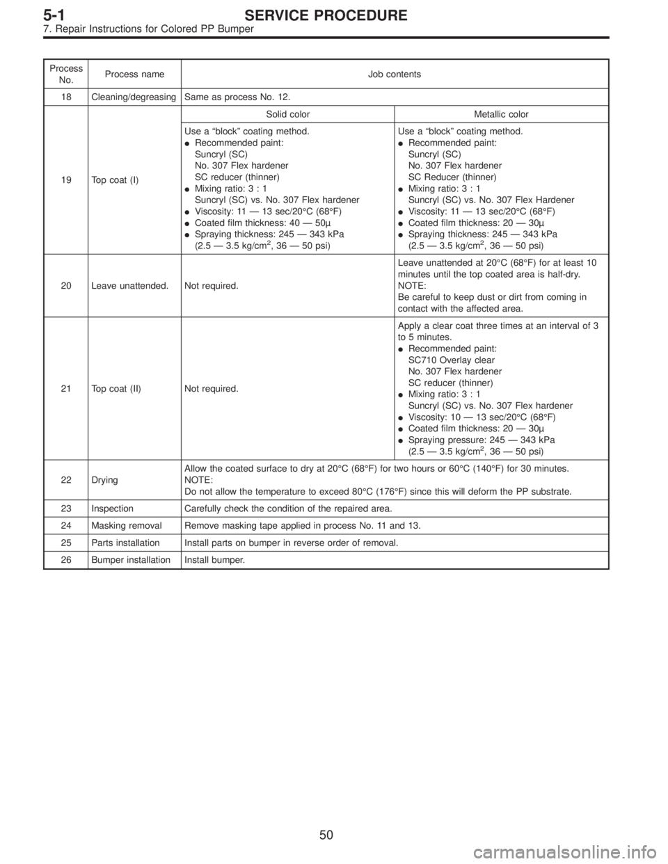
Process
No.Process name Job contents
18 Cleaning/degreasing Same as process No. 12.
19 Top coat (I)Solid color Metallic color
Use a“block”coating method.
�Recommended paint:
Suncryl (SC)
No. 307 Flex hardener
SC reducer (thinner)
�Mixing ratio:3:1
Suncryl (SC) vs. No. 307 Flex hardener
�Viscosity: 11—13 sec/20°C (68°F)
�Coated film thickness: 40—50µ
�Spraying thickness: 245—343 kPa
(2.5—3.5 kg/cm
2,36—50 psi)Use a“block”coating method.
�Recommended paint:
Suncryl (SC)
No. 307 Flex hardener
SC Reducer (thinner)
�Mixing ratio:3:1
Suncryl (SC) vs. No. 307 Flex Hardener
�Viscosity: 11—13 sec/20°C (68°F)
�Coated film thickness: 20—30µ
�Spraying thickness: 245—343 kPa
(2.5—3.5 kg/cm2,36—50 psi)
20 Leave unattended. Not required.Leave unattended at 20°C (68°F) for at least 10
minutes until the top coated area is half-dry.
NOTE:
Be careful to keep dust or dirt from coming in
contact with the affected area.
21 Top coat (II) Not required.Apply a clear coat three times at an interval of 3
to 5 minutes.
�Recommended paint:
SC710 Overlay clear
No. 307 Flex hardener
SC reducer (thinner)
�Mixing ratio:3:1
Suncryl (SC) vs. No. 307 Flex hardener
�Viscosity: 10—13 sec/20°C (68°F)
�Coated film thickness: 20—30µ
�Spraying pressure: 245—343 kPa
(2.5—3.5 kg/cm
2,36—50 psi)
22 DryingAllow the coated surface to dry at 20°C (68°F) for two hours or 60°C (140°F) for 30 minutes.
NOTE:
Do not allow the temperature to exceed 80°C (176°F) since this will deform the PP substrate.
23 Inspection Carefully check the condition of the repaired area.
24 Masking removal Remove masking tape applied in process No. 11 and 13.
25 Parts installation Install parts on bumper in reverse order of removal.
26 Bumper installation Install bumper.
50
5-1SERVICE PROCEDURE
7. Repair Instructions for Colored PP Bumper