Page 1840 of 2890
ContentConnector
No.Terminal
No.Signal (V)
Note
Ignition SW ON
(Engine OFF)Engine ON (Idling)
AT diagnosis input signal B84 80Less than 1)More
than 4Less than 1)More
than 4Waveform
GND (sensors) B84 20 0 0—
GND (injectors) B8469
00—
95
GND (ignition system) B84 94 0 0—
GND (power supply) B8419
00—
46
GND (control systems) B8417
00—
18
GND (oxygen sensor
heater)B84 42 0 0—
2. ENGINE CONDITION DATA
Content Model Specified data
Mass air flow2200 cc1.7—3.3 (g/sec): Idling
7.1—14.2 (g/sec): 2,500 rpm racing
2500 cc2.2—4.2 (g/sec): Idling
8.6—14.5 (g/sec): 2,500 rpm racing
Engine load2200 cc1.6—2.9 (%): Idling
6.4—12.8 (%): 2,500 rpm racing
2500 cc1.9—3.5 (%): Idling
7.2—12.1 (%): 2,500 rpm racing
Measuring condition:
�After warm-up the engine.
�Gear position is in“N”or“P”position.
�A/C is turned OFF.
�All accessory switches are turned OFF.
72
2-7ON-BOARD DIAGNOSTICS II SYSTEM
5. Specified Data
Page 1842 of 2890

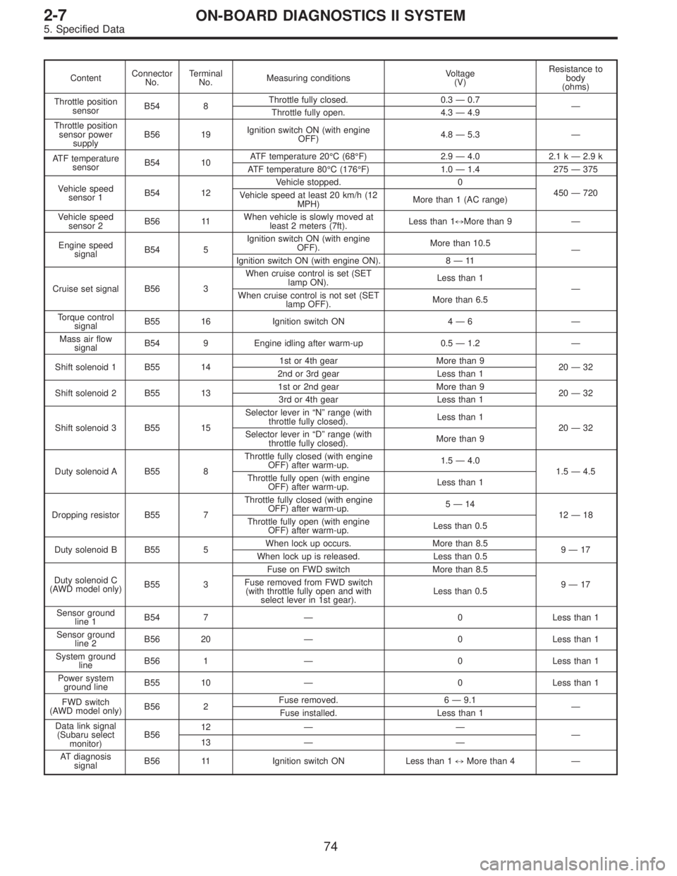
ContentConnector
No.Terminal
No.Measuring conditionsVoltage
(V)Resistance to
body
(ohms)
Throttle position
sensorB54 8Throttle fully closed. 0.3—0.7
—
Throttle fully open. 4.3—4.9
Throttle position
sensor power
supplyB56 19Ignition switch ON (with engine
OFF)4.8—5.3—
ATF temperature
sensorB54 10ATF temperature 20°C(68°F) 2.9—4.0 2.1 k—2.9 k
ATF temperature 80°C (176°F) 1.0—1.4 275—375
Vehicle speed
sensor 1B54 12Vehicle stopped. 0
450—720
Vehicle speed at least 20 km/h (12
MPH)More than 1 (AC range)
Vehicle speed
sensor 2B56 11When vehicle is slowly moved at
least 2 meters (7ft).Less than 1)More than 9—
Engine speed
signalB54 5Ignition switch ON (with engine
OFF).More than 10.5
—
Ignition switch ON (with engine ON). 8—11
Cruise set signal B56 3When cruise control is set (SET
lamp ON).Less than 1
—
When cruise control is not set (SET
lamp OFF).More than 6.5
Torque control
signalB55 16 Ignition switch ON 4—6—
Mass air flow
signalB54 9 Engine idling after warm-up 0.5—1.2—
Shift solenoid 1 B55 141st or 4th gear More than 9
20—32
2nd or 3rd gear Less than 1
Shift solenoid 2 B55 131st or 2nd gear More than 9
20—32
3rd or 4th gear Less than 1
Shift solenoid 3 B55 15Selector lever in“N”range (with
throttle fully closed).Less than 1
20—32
Selector lever in“D”range (with
throttle fully closed).More than 9
Duty solenoid A B55 8Throttle fully closed (with engine
OFF) after warm-up.1.5—4.0
1.5—4.5
Throttle fully open (with engine
OFF) after warm-up.Less than 1
Dropping resistor B55 7Throttle fully closed (with engine
OFF) after warm-up.5—14
12—18
Throttle fully open (with engine
OFF) after warm-up.Less than 0.5
Duty solenoid B B55 5When lock up occurs. More than 8.5
9—17
When lock up is released. Less than 0.5
Duty solenoid C
(AWD model only)B55 3Fuse on FWD switch More than 8.5
9—17 Fuse removed from FWD switch
(with throttle fully open and with
select lever in 1st gear).Less than 0.5
Sensor ground
line 1B54 7—0 Less than 1
Sensor ground
line 2B56 20—0 Less than 1
System ground
lineB56 1—0 Less than 1
Power system
ground lineB55 10—0 Less than 1
FWD switch
(AWD model only)B56 2Fuse removed. 6—9.1
—
Fuse installed. Less than 1
Data link signal
(Subaru select
monitor)B5612——
—
13——
AT diagnosis
signalB56 11 Ignition switch ON Less than 1)More than 4—
74
2-7ON-BOARD DIAGNOSTICS II SYSTEM
5. Specified Data
Page 1845 of 2890
2. CHECK LIST FOR INTERVIEW
Check the following items when problem occurred.
Customer’s name Engine no.
Date of sale Fuel brand
Date of repair Odometer readingkm
miles
Vin no.
Weather�Fine�Cloudy�Rainy�Snowy�Various/Other
Outdoor Temperature�Hot�Warm�Cool�Cold (approx.°F/°C)
Place�Highway�Suburbs�Inner City�Uphill�Downhill
�Rough road�Other
Engine Temp.�Cold�Warming-up�After warming-up�Any temp.�Other
Engine speed
0 2,000 4,000 6,000 8,000 rpm
Driving conditions�Not affected
�At starting�While idling�At racing
�While accelerating�While cruising
�While decelerating�While turning (RH/LH)
Vehicle speed
0 102030405060MPH
Headlight�ON /�OFF
Blower�ON /�OFF
A/C compressor�ON /�OFF
Cooling fan�ON /�OFF
Front wiper�ON /�OFF
Rear wiper�ON /�OFF
Rear defogger�ON /�OFF
Radio�ON /�OFF
CD/Cassette�ON /�OFF
Car phone�ON /�OFF
CB
NOTE: Use copies of this page for interviewing customers.
77
2-7ON-BOARD DIAGNOSTICS II SYSTEM
6. Basic Diagnostics Procedure
Page 1893 of 2890
OBD0142
B: DTC P0100
—MASS AIR FLOW SENSOR CIRCUIT
MALFUNCTION (QA)—
DTC DETECTING CONDITION:
�Immediately at fault recognition
TROUBLE SYMPTOM:
�Erroneous idling
�Engine stalls.
�Poor driving performance
10B1Connect Subaru Select Monitor or the OBD-II
general scan tool, and read data.�10B5Check harness between ECM and mass air
flow sensor connector.
10B2Check input signal for ECM. (Using voltage
meter and Subaru Select Monitor.)
10B3Check power supply to mass air flow sensor.
10B4Check harness between ECM and mass air
flow sensor connector.
CAUTION:
After repair or replacement of faulty parts, conduct
CLEAR MEMORY and INSPECTION MODES.
�
�
�
125
2-7ON-BOARD DIAGNOSTICS II SYSTEM
10. Diagnostics Chart with Trouble Code
Page 1896 of 2890

OBD0145A
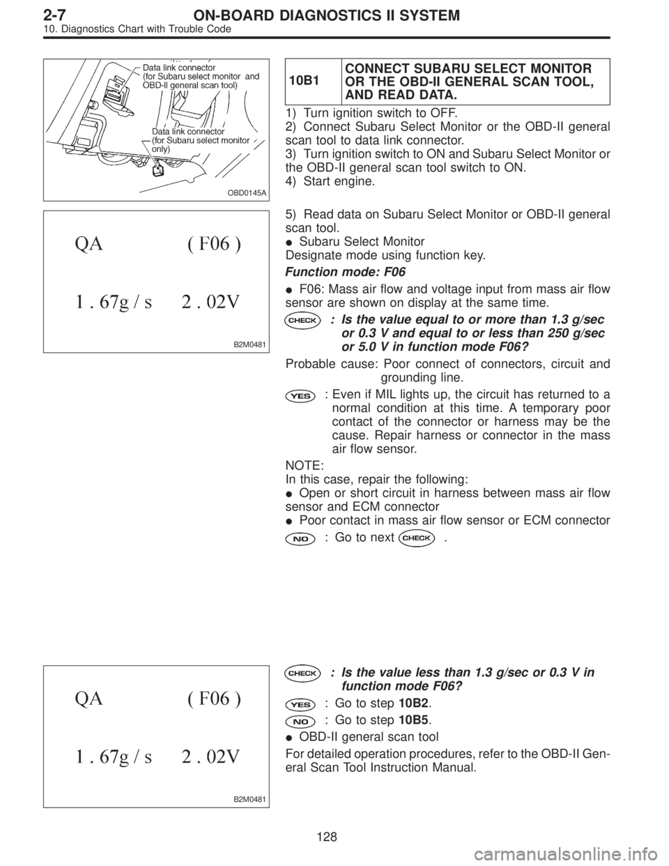
10B1CONNECT SUBARU SELECT MONITOR
OR THE OBD-II GENERAL SCAN TOOL,
AND READ DATA.
1) Turn ignition switch to OFF.
2) Connect Subaru Select Monitor or the OBD-II general
scan tool to data link connector.
3) Turn ignition switch to ON and Subaru Select Monitor or
the OBD-II general scan tool switch to ON.
4) Start engine.
B2M0481
5) Read data on Subaru Select Monitor or OBD-II general
scan tool.
�Subaru Select Monitor
Designate mode using function key.
Function mode: F06
�F06: Mass air flow and voltage input from mass air flow
sensor are shown on display at the same time.
: Is the value equal to or more than 1.3 g/sec
or 0.3 V and equal to or less than 250 g/sec
or 5.0 V in function mode F06?
Probable cause: Poor connect of connectors, circuit and
grounding line.
: Even if MIL lights up, the circuit has returned to a
normal condition at this time. A temporary poor
contact of the connector or harness may be the
cause. Repair harness or connector in the mass
air flow sensor.
NOTE:
In this case, repair the following:
�Open or short circuit in harness between mass air flow
sensor and ECM connector
�Poor contact in mass air flow sensor or ECM connector
: Go to next.
B2M0481
: Is the value less than 1.3 g/sec or 0.3 V in
function mode F06?
: Go to step10B2.
: Go to step10B5.
�OBD-II general scan tool
For detailed operation procedures, refer to the OBD-II Gen-
eral Scan Tool Instruction Manual.
128
2-7ON-BOARD DIAGNOSTICS II SYSTEM
10. Diagnostics Chart with Trouble Code
Page 1900 of 2890
OBD0152
C: DTC P0101
—MASS AIR FLOW SENSOR CIRCUIT
RANGE/PERFORMANCE PROBLEM
(QA
—R)—
DTC DETECTING CONDITION:
�Two consecutive trips with fault
TROUBLE SYMPTOM:
�Erroneous idling
�Engine stalls.
�Poor driving performance
10C1Check DTC P0100 on display.
CAUTION:
After repair or replacement of faulty parts, conduct
CLEAR MEMORY and INSPECTION MODES.
WIRING DIAGRAM:
�LHD Model
B2M0531
132
2-7ON-BOARD DIAGNOSTICS II SYSTEM
10. Diagnostics Chart with Trouble Code
Page 1902 of 2890
OBD0154
D: DTC P0105
—PRESSURE SENSOR CIRCUIT
MALFUNCTION (P
—S)—
DTC DETECTING CONDITION:
�Immediately at fault recognition
10D1Connect Subaru Select Monitor or the OBD-II
general scan tool, and read data.
�
10D2Check input signal for ECM. (Using voltage
meter and Subaru Select Monitor.)
10D3Check harness between ECM and pressure
sensor connector.
10D4Check harness between ECM and pressure
sensor connector.
CAUTION:
After repair or replacement of faulty parts, conduct
CLEAR MEMORY and INSPECTION MODES.
�
�
134
2-7ON-BOARD DIAGNOSTICS II SYSTEM
10. Diagnostics Chart with Trouble Code
Page 1910 of 2890
B2M0654
E: DTC P0106
—PRESSURE SENSOR CIRCUIT
RANGE/PERFORMANCE PROBLEM (PS
—R)
—
DTC DETECTING CONDITION:
�Two consecutive trips with fault
10E1Check DTC P0105 or P1102 on display.
10E2Check data for control.
10E3Check vacuum hose.
10E4Check pressure sources switching solenoid
valve.
CAUTION:
After repair or replacement of faulty parts, conduct
CLEAR MEMORY and INSPECTION MODES.
�
�
�
142
2-7ON-BOARD DIAGNOSTICS II SYSTEM
10. Diagnostics Chart with Trouble Code