Page 1355 of 2890
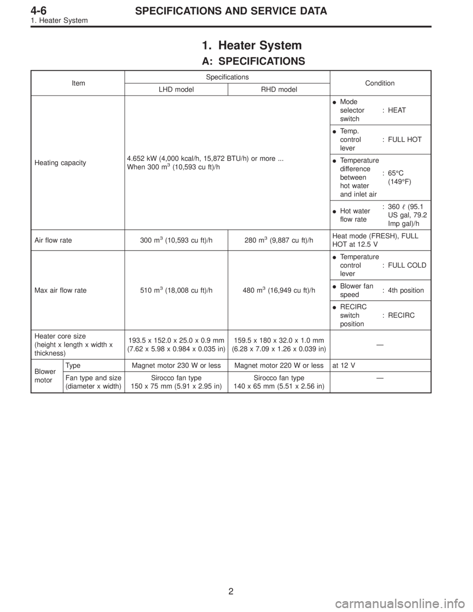
1. Heater System
A: SPECIFICATIONS
ItemSpecifications
Condition
LHD model RHD model
Heating capacity4.652 kW (4,000 kcal/h, 15,872 BTU/h) or more ...
When 300 m
3(10,593 cu ft)/h�Mode
selector
switch: HEAT
�Te m p .
control
lever: FULL HOT
�Temperature
difference
between
hot water
and inlet air:65°C
(149°F)
�Hot water
flow rate: 360�(95.1
US gal, 79.2
Imp gal)/h
Air flow rate 300 m
3(10,593 cu ft)/h 280 m3(9,887 cu ft)/hHeat mode (FRESH), FULL
HOT at 12.5 V
Max air flow rate 510 m
3(18,008 cu ft)/h 480 m3(16,949 cu ft)/h�Temperature
control
lever: FULL COLD
�Blower fan
speed: 4th position
�RECIRC
switch
position: RECIRC
Heater core size
(height x length x width x
thickness)193.5 x 152.0 x 25.0 x 0.9 mm
(7.62 x 5.98 x 0.984 x 0.035 in)159.5 x 180 x 32.0 x 1.0 mm
(6.28 x 7.09 x 1.26 x 0.039 in)—
Blower
motorType Magnet motor 230 W or less Magnet motor 220 W or less at 12 V
Fan type and size
(diameter x width)Sirocco fan type
150 x 75 mm (5.91 x 2.95 in)Sirocco fan type
140 x 65 mm (5.51 x 2.56 in)—
2
4-6SPECIFICATIONS AND SERVICE DATA
1. Heater System
Page 1375 of 2890
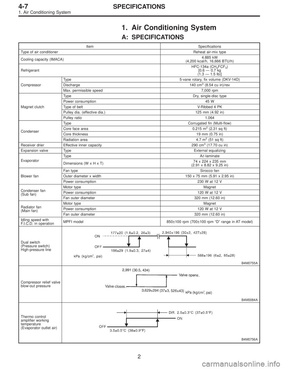
1. Air Conditioning System
A: SPECIFICATIONS
Item Specifications
Type of air conditionerReheat air-mix type
Cooling capacity (IMACA)4.885 kW
(4,200 kcal/h, 16,666 BTU/h)
RefrigerantHFC-134a (CH
2FCF3)
[0.6 — 0.7 kg
(1.3 — 1.5 lb)]
CompressorType 5-vane rotary, fix volume (DKV-14D)
Discharge 140 cm
3(8.54 cu in)/rev
Max. permissible speed 7,000 rpm
Magnet clutchTy p eDry, single-disc type
Power consumption 45 W
Type of belt V-Ribbed 4 PK
Pulley dia. (effective dia.) 125 mm (4.92 in)
Pulley ratio1.064
CondenserType Corrugated fin (Multi-flow)
Core face area 0.215 m
2(2.31 sq ft)
Core thickness 19 mm (0.75 in)
Radiation area 4.7 m
2(51 sq ft)
Receiver drier Effective inner capacity 290 cm3(17.70 cu in)
Expansion valve TypeExternal equalizing
EvaporatorTy p eA�-laminate
Dimensions (W x H x T)74 x 224 x 235 mm
(2.91 x 8.82 x 9.25 in)
Blower fanFan typeSirocco fan
Outer diameter x width 150 x 75 mm (5.91 x 2.95 in)
Power consumption 230 W at 12 V
Condenser fan
(Sub fan)Motor typeMagnet
Power consumption 120 W at 12 V
Fan outer diameter 320 mm (12.60 in)
Radiator fan
(Main fan)Motor typeMagnet
Power consumption 120 W at 12 V
Fan outer diameter 320 mm (12.60 in)
Idling speed with
F.I.C.D. in operationMPFI model 850±100 rpm (700±100 rpm “D” range in AT model)
Dual switch
(Pressure switch)
High-pressure line
B4M0755A
Compressor relief valve
blow-out pressure
B4M0084A
Thermo control
amplifier working
temperature
(Evaporator outlet air)
B4M0756A
2
4-7SPECIFICATIONS
1. Air Conditioning System
Page 1376 of 2890
1. Air Conditioning System
1. LHD MODEL
B4M0757A
�1Receiver drier bracket
�
2Pipe (Receiver drier—Evaporator module)
�
3Receiver drier
�
4Evaporator unit
�
5Hose (Low-pressure)
�
6A/C relay
�
7Fuse
�
8Hose (High-pressure)
�
9Compressor
�
10Condenser
�
11Pipe (Condenser—Receiver drier)
Tightening torque: N⋅m (kg-m, ft-lb)
T1: 7.4±2.0 (0.75±0.2, 5.4±1.4)
T2: 15±5 (1.5±0.5, 10.8±3.6)
T3: 15±3 (1.5±0.3, 10.8±2.2)
T4: 25±5 (2.5±0.5, 18.1±3.6)
3
4-7COMPONENT PARTS
1. Air Conditioning System
Page 1377 of 2890
2. RHD MODEL
B4M0683A
�1Receiver drier
�
2Pipe (Receiver drier—Evaporator module)
�
3Evaporator unit
�
4Hose (Low-pressure)
�
5A/C relay
�
6Fuse
�
7Hose (High-pressure)
�
8Compressor
�
9Condenser
�
10Pipe (Condenser—Receiver drier)
Tightening torque: N⋅m (kg-m, ft-lb)
T1: 7.4±2.0 (0.75±0.2, 5.4±1.4)
T2: 15±3 (1.5±0.3, 10.8±2.2)
T3: 15±5 (1.5±0.5, 10.8±3.6)
T4: 25±5 (2.5±0.5, 18.1±3.6)
4
4-7COMPONENT PARTS
1. Air Conditioning System
Page 1382 of 2890
1. Safety Precautions
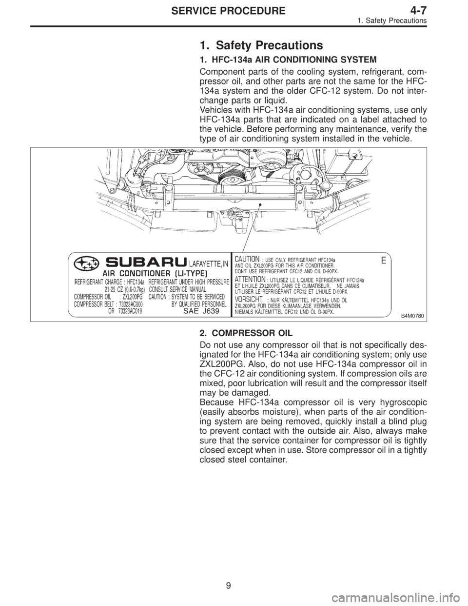
1. HFC-134a AIR CONDITIONING SYSTEM
Component parts of the cooling system, refrigerant, com-
pressor oil, and other parts are not the same for the HFC-
134a system and the older CFC-12 system. Do not inter-
change parts or liquid.
Vehicles with HFC-134a air conditioning systems, use only
HFC-134a parts that are indicated on a label attached to
the vehicle. Before performing any maintenance, verify the
type of air conditioning system installed in the vehicle.
B4M0780
2. COMPRESSOR OIL
Do not use any compressor oil that is not specifically des-
ignated for the HFC-134a air conditioning system; only use
ZXL200PG. Also, do not use HFC-134a compressor oil in
the CFC-12 air conditioning system. If compression oils are
mixed, poor lubrication will result and the compressor itself
may be damaged.
Because HFC-134a compressor oil is very hygroscopic
(easily absorbs moisture), when parts of the air condition-
ing system are being removed, quickly install a blind plug
to prevent contact with the outside air. Also, always make
sure that the service container for compressor oil is tightly
closed except when in use. Store compressor oil in a tightly
closed steel container.
9
4-7SERVICE PROCEDURE
1. Safety Precautions
Page 1383 of 2890
3. REFRIGERANT
Do not put CFC-12 refrigerant into a HFC-134a air condi-
tioning system. Also, do not put HFC-134a refrigerant into
a CFC-12 air conditioning system. If the wrong refrigerant
is used, poor lubrication will result and the compressor
itself may be destroyed.
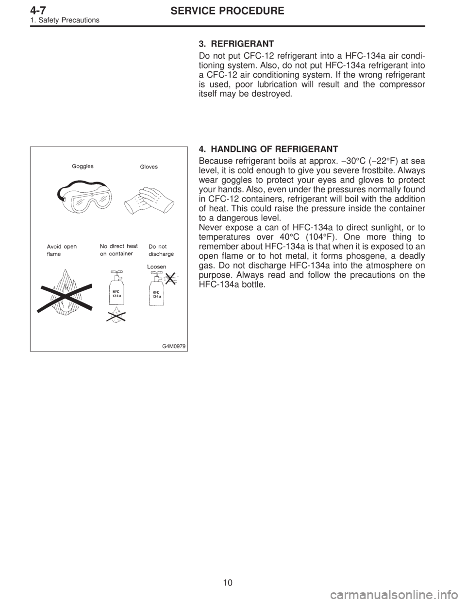
G4M0979
4. HANDLING OF REFRIGERANT
Because refrigerant boils at approx. �30°C (�22°F) at sea
level, it is cold enough to give you severe frostbite. Always
wear goggles to protect your eyes and gloves to protect
your hands. Also, even under the pressures normally found
in CFC-12 containers, refrigerant will boil with the addition
of heat. This could raise the pressure inside the container
to a dangerous level.
Never expose a can of HFC-134a to direct sunlight, or to
temperatures over 40°C (104°F). One more thing to
remember about HFC-134a is that when it is exposed to an
open flame or to hot metal, it forms phosgene, a deadly
gas. Do not discharge HFC-134a into the atmosphere on
purpose. Always read and follow the precautions on the
HFC-134a bottle.
10
4-7SERVICE PROCEDURE
1. Safety Precautions
Page 1396 of 2890
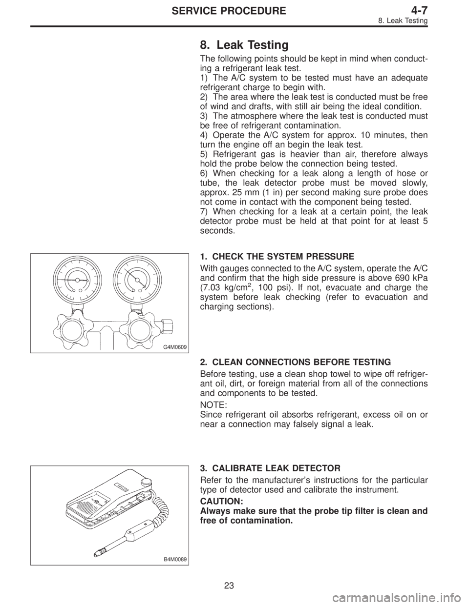
8. Leak Testing
The following points should be kept in mind when conduct-
ing a refrigerant leak test.
1) The A/C system to be tested must have an adequate
refrigerant charge to begin with.
2) The area where the leak test is conducted must be free
of wind and drafts, with still air being the ideal condition.
3) The atmosphere where the leak test is conducted must
be free of refrigerant contamination.
4) Operate the A/C system for approx. 10 minutes, then
turn the engine off an begin the leak test.
5) Refrigerant gas is heavier than air, therefore always
hold the probe below the connection being tested.
6) When checking for a leak along a length of hose or
tube, the leak detector probe must be moved slowly,
approx. 25 mm (1 in) per second making sure probe does
not come in contact with the component being tested.
7) When checking for a leak at a certain point, the leak
detector probe must be held at that point for at least 5
seconds.
G4M0609
1. CHECK THE SYSTEM PRESSURE
With gauges connected to the A/C system, operate the A/C
and confirm that the high side pressure is above 690 kPa
(7.03 kg/cm
2, 100 psi). If not, evacuate and charge the
system before leak checking (refer to evacuation and
charging sections).
2. CLEAN CONNECTIONS BEFORE TESTING
Before testing, use a clean shop towel to wipe off refriger-
ant oil, dirt, or foreign material from all of the connections
and components to be tested.
NOTE:
Since refrigerant oil absorbs refrigerant, excess oil on or
near a connection may falsely signal a leak.
B4M0089
3. CALIBRATE LEAK DETECTOR
Refer to the manufacturer’s instructions for the particular
type of detector used and calibrate the instrument.
CAUTION:
Always make sure that the probe tip filter is clean and
free of contamination.
23
4-7SERVICE PROCEDURE
8. Leak Testing
Page 1402 of 2890
10. Performance Test
1. VEHICLE SET UP
In order to obtain meaningful test results, the vehicle must
be set up to meet the following conditions:
1) Vehicle in shade
2) No wind
3) All vehicle doors closed
4) Front windows opened
5) Hood opened
6) Engine speed set at 1,500 rpm.
7) A/C ON
8) Temperature control lever—Maximum cold
9) Air source—Recirculation
10) Blower speed—4th position (High)
11) Operate A/C for 10 minutes (Minimum) before taking
measurement.
2. MEASUREMENTS
After 10 minutes (Minimum) of A/C operation and using
accurate test equipment, take the following measurements
(in order):
1) Evaporator intake air temperature at recirculation door.
2) Evaporator discharge air temperature at center grill.
3) Condenser (Ambient) intake air temperature measured
0.9 m (3 ft) in front and in line with the center of the con-
denser.
4) Suction (Low) side pressure
5) Discharge (High) side pressure
NOTE:
If only one thermometer is available; 1) take the ambient
measurement first; then 2) the intake air; and 3) dis-
charge air temperature.
28
4-7SERVICE PROCEDURE
10. Performance Test