Page 610 of 2890
B: LO MODE OPERATION (WITH A/C MODEL)
CONDITION:
Condition (1) :
�Engine coolant temperature is below 89°C (192°F).
�A/C switch is turned ON.
�Vehicle speed is below 10 km/h (6 MPH).
Condition (2) :
�Engine coolant temperature is above 95°C (203°F).
�A/C switch is turned OFF.
�Vehicle speed is below 10 km/h (6 MPH).
TROUBLE SYMPTOM:
�Radiator main fan does not rotate at LO speed under
conditions (1) and (2) above.
1. Check power supply to main fan relay-1.
OK
�Not OK
Melted fuse (in A/C relay holder),repair the
shorted part of the circuit,replace fuse.
2. Check main fan relay-1.
OK
�Not OK
Replace main fan relay-1.
3. Check harness connector between main fan
relay-1 and main fan motor.
OK
�Not OK
Repair or replace wiring harness.
4. Check ground circuit of main fan motor.
OK
�Not OK
Repair or replace wiring harness.
5. Check main fan motor.
OK
�Not OK
Replace main fan motor.
Refer to 2-7 On-Board Diagnostics II System.
�
�
�
�
�
24
2-5DIAGNOSTICS
2. Radiator Main Fan
Page 613 of 2890
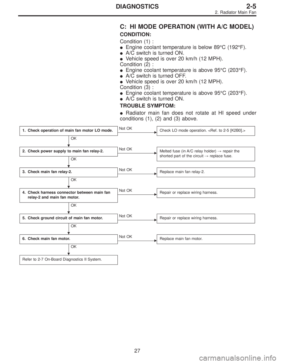
C: HI MODE OPERATION (WITH A/C MODEL)
CONDITION:
Condition (1) :
�Engine coolant temperature is below 89°C (192°F).
�A/C switch is turned ON.
�Vehicle speed is over 20 km/h (12 MPH).
Condition (2) :
�Engine coolant temperature is above 95°C (203°F).
�A/C switch is turned OFF.
�Vehicle speed is over 20 km/h (12 MPH).
Condition (3) :
�Engine coolant temperature is above 95°C (203°F).
�A/C switch is turned ON.
TROUBLE SYMPTOM:
�Radiator main fan does not rotate at HI speed under
conditions (1), (2) and (3) above.
1. Check operation of main fan motor LO mode.
OK
�Not OK
Check LO mode operation.
2. Check power supply to main fan relay-2.
OK
�Not OK
Melted fuse (in A/C relay holder),repair the
shorted part of the circuit,replace fuse.
3. Check main fan relay-2.
OK
�Not OK
Replace main fan relay-2.
4. Check harness connector between main fan
relay-2 and main fan motor.
OK
�Not OK
Repair or replace wiring harness.
5. Check ground circuit of main fan motor.
OK
�Not OK
Repair or replace wiring harness.
6. Check main fan motor.
OK
�Not OK
Replace main fan motor.
Refer to 2-7 On-Board Diagnostics II System.
�
�
�
�
�
�
27
2-5DIAGNOSTICS
2. Radiator Main Fan
Page 617 of 2890
A: LO MODE OPERATION
CONDITION:
Condition (1) :
�Engine coolant temperature is below 89°C (192°F).
�A/C switch is turned ON.
�Vehicle speed is below 10 km/h (6 MPH).
Condition (2) :
�Engine coolant temperature is above 95°C (203°F).
�A/C switch is turned OFF.
�Vehicle speed is below 10 km/h (6 MPH).
TROUBLE SYMPTOM:
�Radiator sub fan does not rotate at LO speed under
conditions (1) and (2) above.
1. Check fuse and power supply.
OK
�Not OK
Melted fuse,repair the shorted part of the circuit
,replace fuse.
2. Check harness connector between fuse and
relay box, and sub fan motor.
OK
�Not OK
Repair or replace wiring harness.
3. Check ground circuit of sub fan motor.
OK
�Not OK
Repair or replace wiring harness.
4. Check sub fan motor.
OK
�Not OK
Replace sub fan motor.
Refer to 2-7 On-Board Diagnostics II System.
�
�
�
�
31
2-5DIAGNOSTICS
3. Radiator Sub Fan (With A/C model only)
Page 619 of 2890
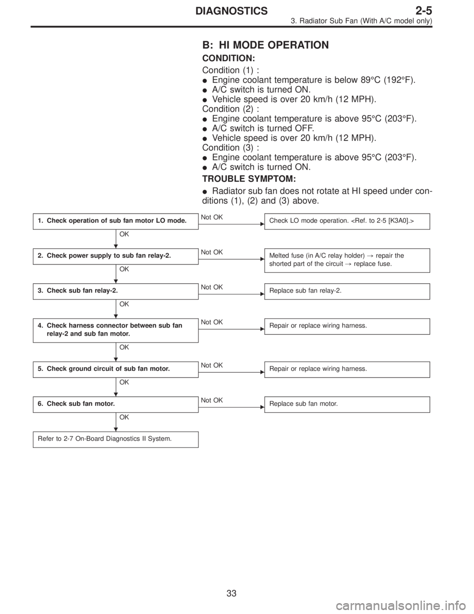
B: HI MODE OPERATION
CONDITION:
Condition (1) :
�Engine coolant temperature is below 89°C (192°F).
�A/C switch is turned ON.
�Vehicle speed is over 20 km/h (12 MPH).
Condition (2) :
�Engine coolant temperature is above 95°C (203°F).
�A/C switch is turned OFF.
�Vehicle speed is over 20 km/h (12 MPH).
Condition (3) :
�Engine coolant temperature is above 95°C (203°F).
�A/C switch is turned ON.
TROUBLE SYMPTOM:
�Radiator sub fan does not rotate at HI speed under con-
ditions (1), (2) and (3) above.
1. Check operation of sub fan motor LO mode.
OK
�Not OK
Check LO mode operation.
2. Check power supply to sub fan relay-2.
OK
�Not OK
Melted fuse (in A/C relay holder),repair the
shorted part of the circuit,replace fuse.
3. Check sub fan relay-2.
OK
�Not OK
Replace sub fan relay-2.
4. Check harness connector between sub fan
relay-2 and sub fan motor.
OK
�Not OK
Repair or replace wiring harness.
5. Check ground circuit of sub fan motor.
OK
�Not OK
Repair or replace wiring harness.
6. Check sub fan motor.
OK
�Not OK
Replace sub fan motor.
Refer to 2-7 On-Board Diagnostics II System.
�
�
�
�
�
�
33
2-5DIAGNOSTICS
3. Radiator Sub Fan (With A/C model only)
Page 651 of 2890
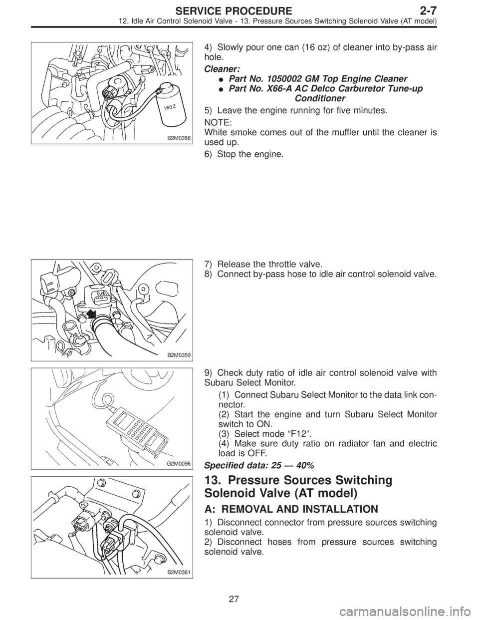
B2M0358
4) Slowly pour one can (16 oz) of cleaner into by-pass air
hole.
Cleaner:
�Part No. 1050002 GM Top Engine Cleaner
�Part No. X66-A AC Delco Carburetor Tune-up
Conditioner
5) Leave the engine running for five minutes.
NOTE:
White smoke comes out of the muffler until the cleaner is
used up.
6) Stop the engine.
B2M0359
7) Release the throttle valve.
8) Connect by-pass hose to idle air control solenoid valve.
G2M0096
9) Check duty ratio of idle air control solenoid valve with
Subaru Select Monitor.
(1) Connect Subaru Select Monitor to the data link con-
nector.
(2) Start the engine and turn Subaru Select Monitor
switch to ON.
(3) Select mode“F12”.
(4) Make sure duty ratio on radiator fan and electric
load is OFF.
Specified data: 25—40%
B2M0361
13. Pressure Sources Switching
Solenoid Valve (AT model)
A: REMOVAL AND INSTALLATION
1) Disconnect connector from pressure sources switching
solenoid valve.
2) Disconnect hoses from pressure sources switching
solenoid valve.
27
2-7SERVICE PROCEDURE
12. Idle Air Control Solenoid Valve - 13. Pressure Sources Switching Solenoid Valve (AT model)
Page 652 of 2890
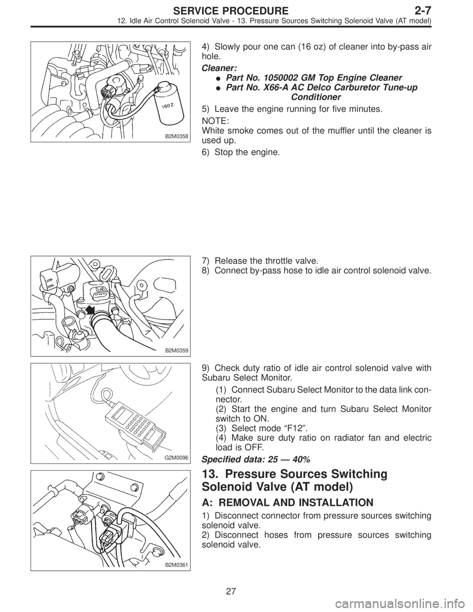
B2M0358
4) Slowly pour one can (16 oz) of cleaner into by-pass air
hole.
Cleaner:
�Part No. 1050002 GM Top Engine Cleaner
�Part No. X66-A AC Delco Carburetor Tune-up
Conditioner
5) Leave the engine running for five minutes.
NOTE:
White smoke comes out of the muffler until the cleaner is
used up.
6) Stop the engine.
B2M0359
7) Release the throttle valve.
8) Connect by-pass hose to idle air control solenoid valve.
G2M0096
9) Check duty ratio of idle air control solenoid valve with
Subaru Select Monitor.
(1) Connect Subaru Select Monitor to the data link con-
nector.
(2) Start the engine and turn Subaru Select Monitor
switch to ON.
(3) Select mode“F12”.
(4) Make sure duty ratio on radiator fan and electric
load is OFF.
Specified data: 25—40%
B2M0361
13. Pressure Sources Switching
Solenoid Valve (AT model)
A: REMOVAL AND INSTALLATION
1) Disconnect connector from pressure sources switching
solenoid valve.
2) Disconnect hoses from pressure sources switching
solenoid valve.
27
2-7SERVICE PROCEDURE
12. Idle Air Control Solenoid Valve - 13. Pressure Sources Switching Solenoid Valve (AT model)
Page 1029 of 2890
G4M0520
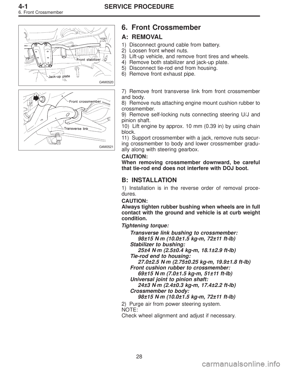
6. Front Crossmember
A: REMOVAL
1) Disconnect ground cable from battery.
2) Loosen front wheel nuts.
3) Lift-up vehicle, and remove front tires and wheels.
4) Remove both stabilizer and jack-up plate.
5) Disconnect tie-rod end from housing.
6) Remove front exhaust pipe.
G4M0521
7) Remove front transverse link from front crossmember
and body.
8) Remove nuts attaching engine mount cushion rubber to
crossmember.
9) Remove self-locking nuts connecting steering U/J and
pinion shaft.
10) Lift engine by approx. 10 mm (0.39 in) by using chain
block.
11) Support crossmember with a jack, remove nuts secur-
ing crossmember to body and lower crossmember gradu-
ally along with steering gearbox.
CAUTION:
When removing crossmember downward, be careful
that tie-rod end does not interfere with DOJ boot.
B: INSTALLATION
1) Installation is in the reverse order of removal proce-
dures.
CAUTION:
Always tighten rubber bushing when wheels are in full
contact with the ground and vehicle is at curb weight
condition.
Tightening torque:
Transverse link bushing to crossmember:
98±15 N⋅m (10.0±1.5 kg-m, 72±11 ft-lb)
Stabilizer to bushing:
25±4 N⋅m (2.5±0.4 kg-m, 18.1±2.9 ft-lb)
Tie-rod end to housing:
27.0±2.5 N⋅m (2.75±0.25 kg-m, 19.9±1.8 ft-lb)
Front cushion rubber to crossmember:
69±15 N⋅m (7.0±1.5 kg-m, 51±11 ft-lb)
Universal joint to pinion shaft:
24±3 N⋅m (2.4±0.3 kg-m, 17.4±2.2 ft-lb)
Crossmember to body:
98±15 N⋅m (10.0±1.5 kg-m, 72±11 ft-lb)
2) Purge air from power steering system.
NOTE:
Check wheel alignment and adjust if necessary.
28
4-1SERVICE PROCEDURE
6. Front Crossmember
Page 1128 of 2890
G4M0114
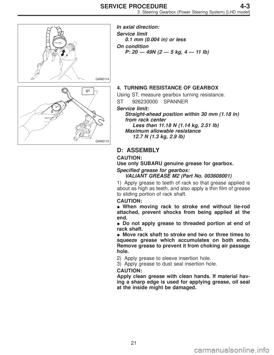
In axial direction:
Service limit
0.1 mm (0.004 in) or less
On condition
P: 20—49N (2—5 kg, 4—11 lb)
G4M0115
4. TURNING RESISTANCE OF GEARBOX
Using ST, measure gearbox turning resistance.
ST 926230000 SPANNER
Service limit:
Straight-ahead position within 30 mm (1.18 in)
from rack center
Less than 11.18 N (1.14 kg, 2.51 lb)
Maximum allowable resistance
12.7 N (1.3 kg, 2.9 lb)
D: ASSEMBLY
CAUTION:
Use only SUBARU genuine grease for gearbox.
Specified grease for gearbox:
VALIANT GREASE M2 (Part No. 003608001)
1) Apply grease to teeth of rack so that grease applied is
about as high as teeth, and also apply a thin film of grease
to sliding portion of rack shaft.
CAUTION:
�When moving rack to stroke end without tie-rod
attached, prevent shocks from being applied at the
end.
�Do not apply grease to threaded portion at end of
rack shaft.
�Move rack shaft to stroke end two or three times to
squeeze grease which accumulates on both ends.
Remove grease to prevent it from choking air passage
hole.
2) Apply grease to sleeve insertion hole.
3) Apply grease to dust seal insertion hole.
CAUTION:
Apply clean grease with clean hands. If material hav-
ing a sharp edge is used for applying grease, oil seal
at the inside might be damaged.
21
4-3SERVICE PROCEDURE
3. Steering Gearbox (Power Steering System) [LHD model]