Page 1580 of 2890
�When storing a removed airbag module (driver side
and passenger side), be sure to place it in parallel with
floor with the pad facing up. Do not place it against a
wall, or place anything on the pad; otherwise, a dan-
gerous condition may be created if the module mal-
functions.
G5M0604
11
5-5SERVICE PROCEDURE
3. Airbag Module
Page 1604 of 2890
�When storing a removed airbag module (driver side
and passenger side), be sure to place it in parallel with
floor with the pad facing up. Do not place it against a
wall, or place anything on the pad; otherwise, a dan-
gerous condition may be created if the module mal-
functions.
G5M0604
11
5-5bSERVICE PROCEDURE
3. Airbag Module
Page 1637 of 2890
G6M0088
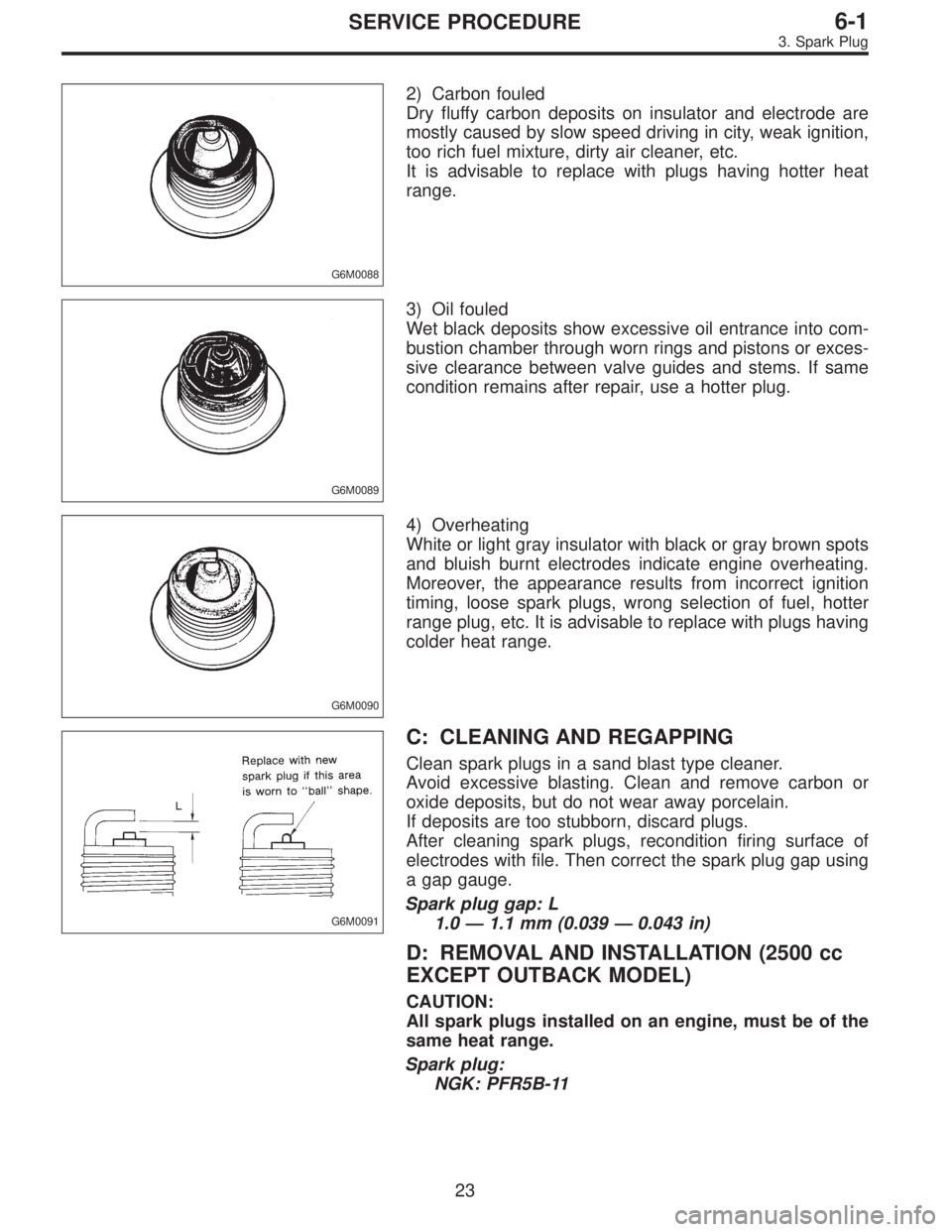
2) Carbon fouled
Dry fluffy carbon deposits on insulator and electrode are
mostly caused by slow speed driving in city, weak ignition,
too rich fuel mixture, dirty air cleaner, etc.
It is advisable to replace with plugs having hotter heat
range.
G6M0089
3) Oil fouled
Wet black deposits show excessive oil entrance into com-
bustion chamber through worn rings and pistons or exces-
sive clearance between valve guides and stems. If same
condition remains after repair, use a hotter plug.
G6M0090
4) Overheating
White or light gray insulator with black or gray brown spots
and bluish burnt electrodes indicate engine overheating.
Moreover, the appearance results from incorrect ignition
timing, loose spark plugs, wrong selection of fuel, hotter
range plug, etc. It is advisable to replace with plugs having
colder heat range.
G6M0091
C: CLEANING AND REGAPPING
Clean spark plugs in a sand blast type cleaner.
Avoid excessive blasting. Clean and remove carbon or
oxide deposits, but do not wear away porcelain.
If deposits are too stubborn, discard plugs.
After cleaning spark plugs, recondition firing surface of
electrodes with file. Then correct the spark plug gap using
a gap gauge.
Spark plug gap: L
1.0—1.1 mm (0.039—0.043 in)
D: REMOVAL AND INSTALLATION (2500 cc
EXCEPT OUTBACK MODEL)
CAUTION:
All spark plugs installed on an engine, must be of the
same heat range.
Spark plug:
NGK: PFR5B-11
23
6-1SERVICE PROCEDURE
3. Spark Plug
Page 1770 of 2890
1. General
1. GENERAL DESCRIPTION
�The on-board diagnostics (OBD) system detects and
indicates a fault in various inputs and outputs of the com-
plex electronic control. CHECK ENGINE malfunction indi-
cator lamp (MIL) in the combination meter indicates occur-
rence of a fault or trouble.
�Further, against such a failure or sensors as may disable
the drive, the fail-safe function is provided to ensure the
minimal driveability.
�The OBD system incorporated with the vehicles within
this engine family complies with Section 1968.1, California
Code of Regulations (OBD-II regulation). The OBD system
monitors the components and the system malfunction
listed in Engine Section which affects on emissions.
�When the system decides that a malfunction occurs, MIL
illuminates. At the same time of the MIL illumination or
blinking, a diagnostic trouble code (DTC) and a freeze
frame engine conditions are stored into on-board com-
puter.
�The OBD system stores freeze frame engine condition
data (engine load, engine coolant temperature, fuel trim,
engine speed and vehicle speed, etc.) into on-board com-
puter when it detects a malfunction first.
�If the OBD system detects the various malfunctions
including the fault of fuel trim or misfire, the OBD system
first stores freeze frame engine conditions about the fuel
trim or misfire.
�When the malfunction does not occur again for three
consecutive trips, MIL is turned off, but DTC remains at
on-board computer.
�The OBD-II system is capable of communication with a
general scan tool (OBD-II general scan tool) formed by ISO
9141 CARB.
�The OBD-II diagnostics procedure is different from the
usual diagnostics procedure. When troubleshooting OBD-II
vehicles, connect Subaru select monitor or the OBD-II gen-
eral scan tool to the vehicle.
A: ENGINE
1. ENGINE AND EMISSION CONTROL SYSTEM
�The Multipoint Fuel Injection (MFI) system is a system
that supplies the optimum air-fuel mixture to the engine for
all the various operating conditions through the use of the
latest electronic technology.
With this system fuel, which is pressurized at a constant
pressure, is injected into the intake air passage of the cyl-
inder head. The injection quantity of fuel is controlled by an
intermittent injection system where the electro-magnetic
injection valve (fuel injector) opens only for a short period
of time, depending on the quantity of air required for one
cycle of operation. In actual operation, the injection quan-
2
2-7ON-BOARD DIAGNOSTICS II SYSTEM
1. General
Page 1771 of 2890
tity is determined by the duration of an electric pulse
applied to the fuel injector and this permits simple, yet
highly precise metering of the fuel.
�Further, all the operating conditions of the engine are
converted into electric signals, and this results in additional
features of the system, such as large improved
adaptability, easier addition of compensating element, etc.
The MFI system also has the following features:
1) Reduced emission of harmful exhaust gases.
2) Reduced in fuel consumption.
3) Increased engine output.
4) Superior acceleration and deceleration.
5) Superior startability and warm-up performance in cold
weather since compensation is made for coolant and
intake air temperature.
3
2-7ON-BOARD DIAGNOSTICS II SYSTEM
1. General
Page 1798 of 2890
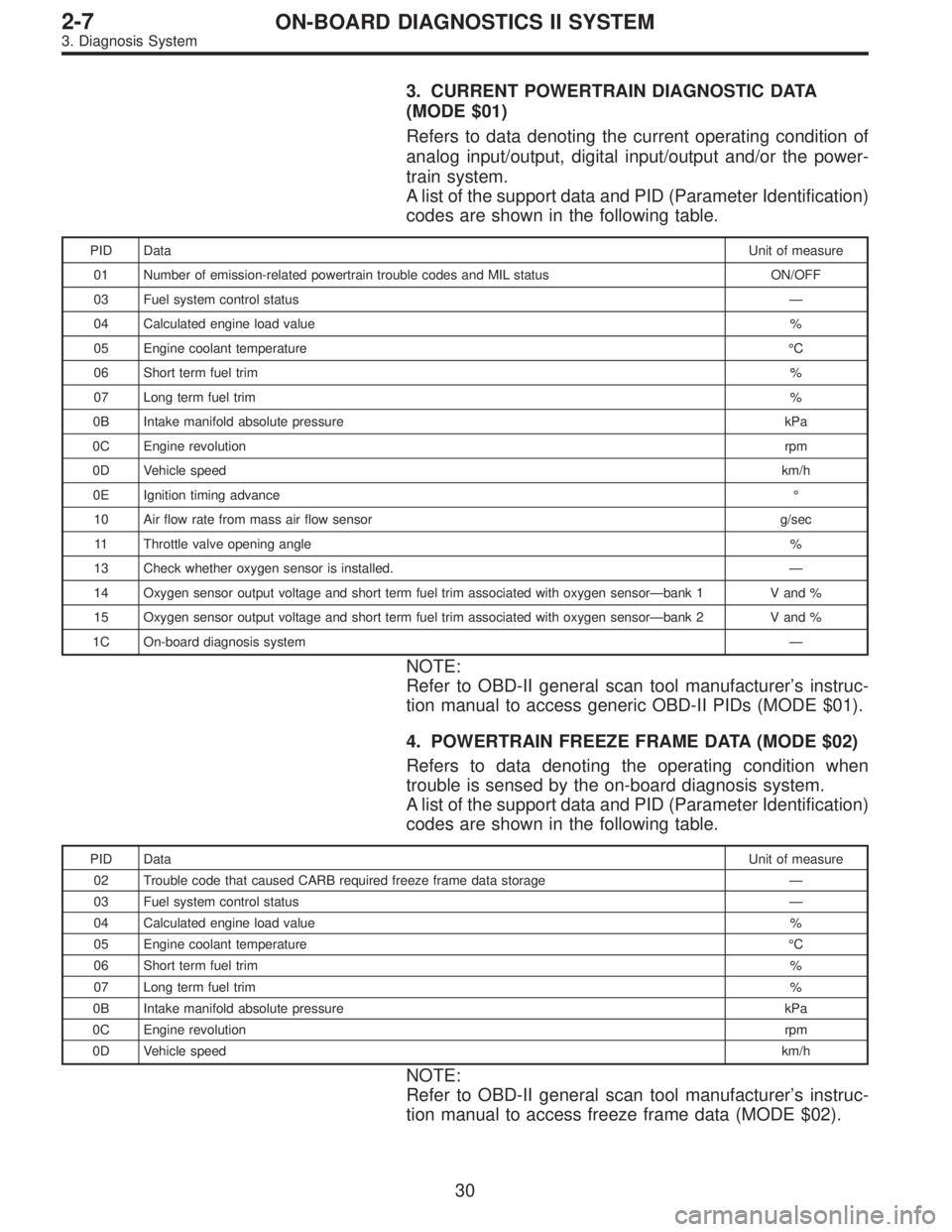
3. CURRENT POWERTRAIN DIAGNOSTIC DATA
(MODE $01)
Refers to data denoting the current operating condition of
analog input/output, digital input/output and/or the power-
train system.
A list of the support data and PID (Parameter Identification)
codes are shown in the following table.
PID DataUnit of measure
01 Number of emission-related powertrain trouble codes and MIL status ON/OFF
03 Fuel system control status—
04 Calculated engine load value%
05 Engine coolant temperature°C
06 Short term fuel trim%
07 Long term fuel trim%
0B Intake manifold absolute pressurekPa
0C Engine revolutionrpm
0D Vehicle speedkm/h
0E Ignition timing advance°
10 Air flow rate from mass air flow sensor g/sec
11 Throttle valve opening angle%
13 Check whether oxygen sensor is installed.—
14 Oxygen sensor output voltage and short term fuel trim associated with oxygen sensor—bank 1 V and %
15 Oxygen sensor output voltage and short term fuel trim associated with oxygen sensor—bank 2 V and %
1C On-board diagnosis system—
NOTE:
Refer to OBD-II general scan tool manufacturer’s instruc-
tion manual to access generic OBD-II PIDs (MODE $01).
4. POWERTRAIN FREEZE FRAME DATA (MODE $02)
Refers to data denoting the operating condition when
trouble is sensed by the on-board diagnosis system.
A list of the support data and PID (Parameter Identification)
codes are shown in the following table.
PID DataUnit of measure
02 Trouble code that caused CARB required freeze frame data storage—
03 Fuel system control status—
04 Calculated engine load value%
05 Engine coolant temperature°C
06 Short term fuel trim%
07 Long term fuel trim%
0B Intake manifold absolute pressurekPa
0C Engine revolutionrpm
0D Vehicle speedkm/h
NOTE:
Refer to OBD-II general scan tool manufacturer’s instruc-
tion manual to access freeze frame data (MODE $02).
30
2-7ON-BOARD DIAGNOSTICS II SYSTEM
3. Diagnosis System
Page 1814 of 2890
H2M1327
39. FUNCTION MODE: F45
—FUEL LEVEL SIGNAL (FLEVEL)—
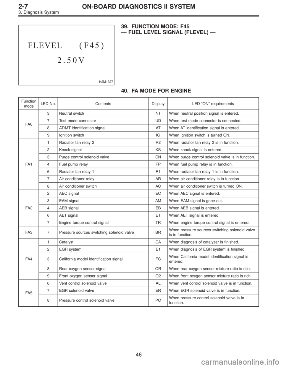
40. FA MODE FOR ENGINE
Function
modeLED No. Contents Display LED“ON”requirements
FA 03 Neutral switch NT When neutral position signal is entered.
7 Test mode connector UD When test mode connector is connected.
8 AT/MT identification signal AT When AT identification signal is entered.
9 Ignition switch IG When ignition switch is turned ON.
FA 11 Radiator fan relay 2 R2 When radiator fan relay 2 is in function.
2 Knock signal KS When knock signal is entered.
3 Purge control solenoid valve CN When purge control solenoid valve is in function.
4 Fuel pump relay FP When fuel pump relay is in function.
6 Radiator fan relay 1 R1 When radiator fan relay 1 is in function.
7 Air conditioner relay AR When air conditioner relay is in function.
8 Air conditioner switch AC When air conditioner switch is turned ON.
FA 22 AEC signal EC When AEC signal is entered.
3 EAM signal AM When EAM signal is gone out.
4 AEB signal EB When AEB signal is entered.
6 AET signal ET When AET signal is entered.
7 Engine torque control signal TR When engine torque control signal is entered.
FA3 7 Pressure sources switching solenoid valve BRWhen pressure sources switching solenoid valve
is in function.
FA 41 Catalyst CA When diagnosis of catalyzer is finished.
2 EGR system E1 When diagnosis of EGR system is finished.
3 California model identification signal FCWhen California model identification signal is
entered.
8 Rear oxygen sensor signal OR When rear oxygen sensor mixture ratio is rich.
9 Front oxygen sensor signal O2 When front oxygen sensor mixture ratio is rich.
FA 56 Vent control solenoid valve AL When vent control solenoid valve is in function.
7 EGR solenoid valve ER When EGR solenoid valve is in function.
8 Pressure control solenoid valve PCWhen pressure control solenoid valve is in
function.
46
2-7ON-BOARD DIAGNOSTICS II SYSTEM
3. Diagnosis System
Page 1826 of 2890
G3M0151
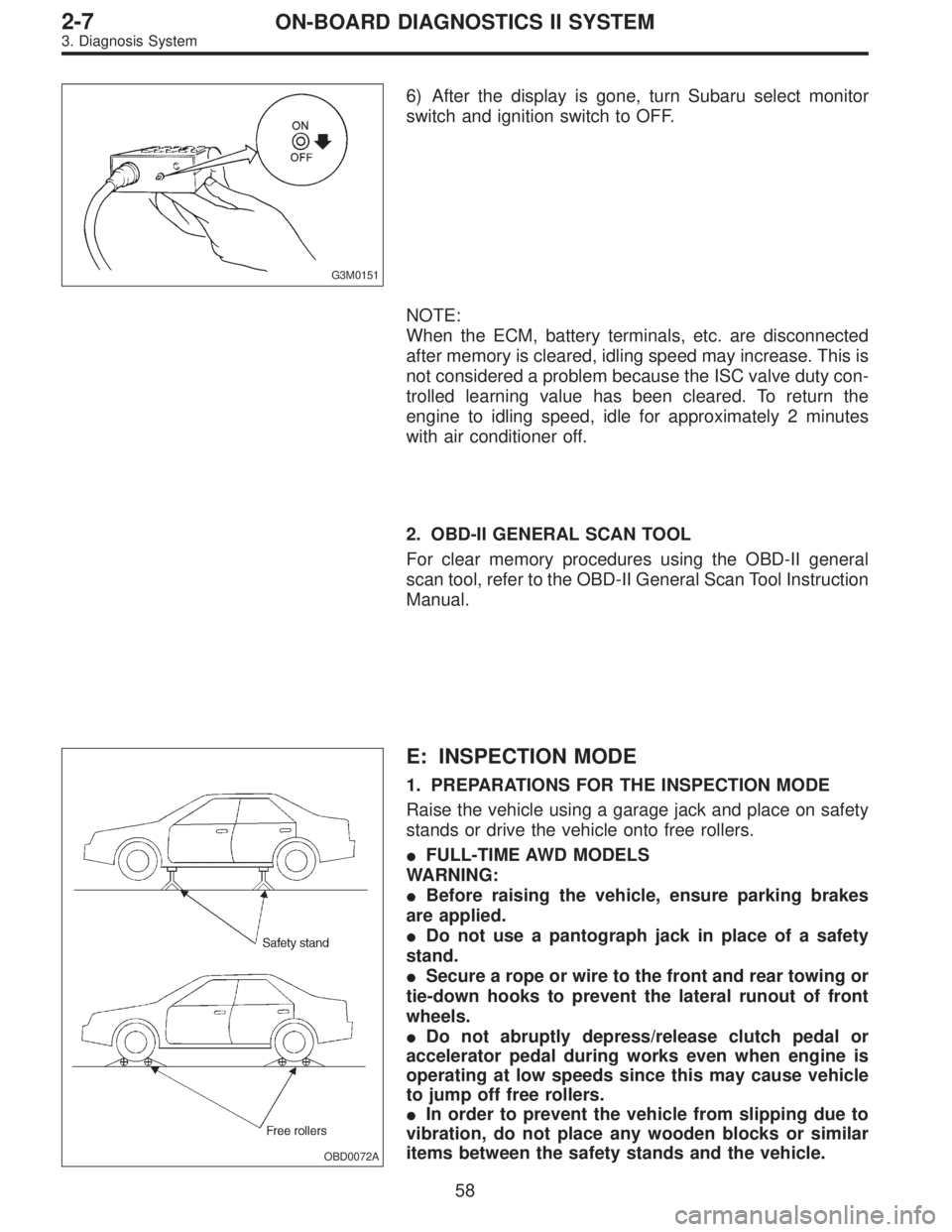
6) After the display is gone, turn Subaru select monitor
switch and ignition switch to OFF.
NOTE:
When the ECM, battery terminals, etc. are disconnected
after memory is cleared, idling speed may increase. This is
not considered a problem because the ISC valve duty con-
trolled learning value has been cleared. To return the
engine to idling speed, idle for approximately 2 minutes
with air conditioner off.
2. OBD-II GENERAL SCAN TOOL
For clear memory procedures using the OBD-II general
scan tool, refer to the OBD-II General Scan Tool Instruction
Manual.
OBD0072A
E: INSPECTION MODE
1. PREPARATIONS FOR THE INSPECTION MODE
Raise the vehicle using a garage jack and place on safety
stands or drive the vehicle onto free rollers.
�FULL-TIME AWD MODELS
WARNING:
�Before raising the vehicle, ensure parking brakes
are applied.
�Do not use a pantograph jack in place of a safety
stand.
�Secure a rope or wire to the front and rear towing or
tie-down hooks to prevent the lateral runout of front
wheels.
�Do not abruptly depress/release clutch pedal or
accelerator pedal during works even when engine is
operating at low speeds since this may cause vehicle
to jump off free rollers.
�In order to prevent the vehicle from slipping due to
vibration, do not place any wooden blocks or similar
items between the safety stands and the vehicle.
58
2-7ON-BOARD DIAGNOSTICS II SYSTEM
3. Diagnosis System