Page 2686 of 2890
 is shorted to power
supply.
�Airbag module harness (Driver) is shorted to power sup-
ply.
�Roll connector is shorted to power supply")
M: TROUBLE CODE 43
DIAGNOSIS:
�Airbag main harness circuit (Driver) is shorted to power
supply.
�Airbag module harness (Driver) is shorted to power sup-
ply.
�Roll connector is shorted to power supply.
�Airbag control module is faulty.
1. Airbag main harness inspection
CAUTION:
Before performing diagnostics on airbag system, turn
ignition switch“OFF”, disconnect battery ground ter-
minal and then wait at least 20 seconds.
After 20 seconds elapse, remove instrument panel
lower cover, and disconnect (AB3) and (AB8), (AB9)
and (AB10).
G5M0559
1. AIRBAG MAIN HARNESS INSPECTION
1) Disconnect connector (AB6) from airbag control module
, and connect it to test harness B2
connector (8B).
2) Connect battery ground cable and turn ignition switch
“ON”(engine off).
3) Measure voltage across each test harness B2 connec-
tor (5B) terminal and chassis ground.
: Connector & terminal
(5B) No. 1 (+)—Chassis ground (�):
Is voltage less than 1 V?
: Go to next.
: Replace airbag main harness.
: Connector & terminal
(5B) No. 14 (+)—Chassis ground (�):
Is voltage less than 1 V?
: Replace airbag control module.
: Replace airbag main harness.
32
5-5bSUPPLEMENTAL RESTRAINT SYSTEM (ELECTRIC SENSOR TYPE)
5. Diagnostics Chart with Trouble Code
Page 2687 of 2890

N: AIRBAG WARNING LIGHT REMAINS ON.
DIAGNOSIS:
�Airbag warning light is faulty.
�Airbag control module to airbag warning light harness
circuit is shorted or open.
�Grounding circuit is faulty.
�Airbag control module is faulty.
�(AB1) and (B31) are not connected properly.
1. Double lock inspection for connectors (AB1)
and (B31)
2. Inspection of body harness, connector and
airbag warning light
3. Grounding circuit inspection
CAUTION:
Before performing diagnostics on airbag system, turn
ignition switch“OFF”, disconnect battery ground
cable and then wait at least 20 seconds.
B5M0122B
1. DOUBLE LOCK INSPECTION FOR CONNECTORS
(AB1) AND (B31)
1) Remove front pillar lower trim (Driver side).
2) Check double lock of connectors (AB1) and (B31).
: Is there poor contact in double lock of con-
nectors (AB1) and (B31)?
: Repair poor contact in double lock of connectors
(AB1) and (B31).
: Go to step2.
�
�
33
5-5bSUPPLEMENTAL RESTRAINT SYSTEM (ELECTRIC SENSOR TYPE)
5. Diagnostics Chart with Trouble Code
Page 2688 of 2890
 Turn ignition switch“OFF”and connect body harness
connector (B31) to test connector A connector (1A).
G5M0455
2) Conne")
B5M0123B
2. INSPECTION OF BODY HARNESS, CONNECTOR
AND AIRBAG WARNING LIGHT
1) Turn ignition switch“OFF”and connect body harness
connector (B31) to test connector A connector (1A).
G5M0455
2) Connect battery ground cable and turn ignition switch
“ON”, (engine off) and connect connectors (3A) and (4A).
: Does the airbag warning light come off?
: Go to step 3).
: Go to next.
B5M0124A
: Is there anything unusual to body harness?
: Repair body harness.
: Replace airbag warning light module�1.
NOTE:
After problem has been eliminated, disconnect connectors
(3A) and (4A).
G5M0559
3) Turn ignition switch“OFF”, disconnect battery ground
cable and then wait at least 20 seconds, and re-connect
connectors (AB1) and (B31).
4) Remove instrument panel lower cover and disconnect
(AB3) with (AB8), then disconnect connector (AB6) from
airbag control module, and connect
it to test harness B2 connector (8B).
G5M0458
5) Connect battery ground cable and turn ignition switch
“ON,”(engine off) and connect connectors (6B) and (7B).
: Does the airbag warning light come on?
: Go to step3.
: Replace airbag main harness.
NOTE:
After problem has been eliminated, disconnect connectors
(6B) and (7B).
34
5-5bSUPPLEMENTAL RESTRAINT SYSTEM (ELECTRIC SENSOR TYPE)
5. Diagnostics Chart with Trouble Code
Page 2689 of 2890
 Turn ignition switch“OFF”, disconnect battery ground
cable and then wait at least 20 seconds. Disconnect con-
nector (AB1) from body harness connector (")
B5M0123B
3. GROUNDING CIRCUIT INSPECTION
1) Turn ignition switch“OFF”, disconnect battery ground
cable and then wait at least 20 seconds. Disconnect con-
nector (AB1) from body harness connector (B31), and con-
nect connector (B31) to test harness A connector (1A).
Measure resistance between connector (5A) terminal and
chassis ground.
: Connector & terminal
(5A) No. 17 (+)—Chassis ground (�):
Is resistance less than 10Ω?
: Go to next.
: Repair body grounding circuit.
: Connector & terminal
(5A) No. 18 (+)—Chassis ground (�):
Is resistance less than 10Ω?
: Go to step 2).
: Repair body grounding circuit.
G5M0559
2) Connect connectors (AB1) and (B31). Disconnect con-
nector (AB6) from airbag control module
[W5A0].>, and connect it to test harness B2 connector
(8B).
3) Measure resistance between each test harness B2 con-
nector (5B) terminal and chassis ground.
: Connector & terminal
(5B) No. 11 (+)—Chassis ground (�):
Is resistance less than 10Ω?
: Go to next.
: Replace airbag main harness.
: Connector & terminal
(5B) No. 12 (+)—Chassis ground (�):
Is resistance less than 10Ω?
: Replace airbag control module.
: Replace airbag main harness.
35
5-5bSUPPLEMENTAL RESTRAINT SYSTEM (ELECTRIC SENSOR TYPE)
5. Diagnostics Chart with Trouble Code
Page 2690 of 2890

O: AIRBAG WARNING LIGHT REMAINS OFF.
DIAGNOSIS:
�Fuse No. 15 is blown.
�Body harness circuit is open.
�Airbag warning light is faulty.
�Airbag main harness is faulty.
�Airbag control module is faulty.
1. Fuse No. 15 inspection
2. Body harness inspection
3. Airbag warning light module (in combination
meter) inspection
4. Airbag main harness inspection
CAUTION:
Before performing diagnostics on airbag system, turn
ignition switch“OFF”, disconnect battery ground
terminal, and then wait at least 20 seconds.
G5M0460
1. FUSE No. 15 INSPECTION
Remove and visually check fuse No. 15.
: Is fuse No. 15 blown?
: Replace fuse No. 15.
If fuse No. 15 blows again, go to step2.
: Go to step2.
2. BODY HARNESS INSPECTION
Turn ignition switch“ON”(engine off) to make sure other
warning lights (in combination meter) illuminate.
: Do all the warning lights (in combination
meter) except airbag warning light come
on?
: Go to step3.
: Repair body harness.
�
�
�
36
5-5bSUPPLEMENTAL RESTRAINT SYSTEM (ELECTRIC SENSOR TYPE)
5. Diagnostics Chart with Trouble Code
Page 2691 of 2890
 INSPECTION
1) Turn ignition switch“OFF”, disconnect battery ground
cable and then wait at least 20 seconds.
2) Disconnect body harnes")
B5M0122B
3. AIRBAG WARNING LIGHT MODULE (IN
COMBINATION METER) INSPECTION
1) Turn ignition switch“OFF”, disconnect battery ground
cable and then wait at least 20 seconds.
2) Disconnect body harness connector (B31) from connec-
tor (AB1).
B5M0124A
3) Connect battery ground cable and turn ignition switch
“ON”(engine off) to make sure airbag warning light illumi-
nates.
: Does the airbag warning light come on?
: Go to step4.
: Replace airbag warning light module�1.
G5M0312
4. AIRBAG MAIN HARNESS INSPECTION
1) Turn ignition switch“OFF”, disconnect battery ground
cable and then wait at least 20 seconds.
2) Connect body harness connector (B31) and connector
(AB1).
3) Disconnect connectors (AB3) and (AB8) below steering
column.
G5M0313
4) Disconnect connector (AB6) from airbag control mod-
ule.
5) Connect battery ground cable and turn ignition switch
“ON”to make sure airbag warning light illuminates.
: Does the airbag warning light come on?
: Replace airbag control module.
: Replace airbag main harness.
37
5-5bSUPPLEMENTAL RESTRAINT SYSTEM (ELECTRIC SENSOR TYPE)
5. Diagnostics Chart with Trouble Code
Page 2692 of 2890
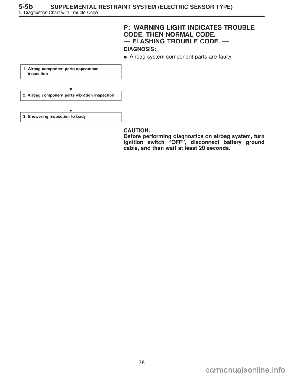
P: WARNING LIGHT INDICATES TROUBLE
CODE, THEN NORMAL CODE.
—FLASHING TROUBLE CODE.—
DIAGNOSIS:
�Airbag system component parts are faulty.
1. Airbag component parts appearance
inspection
2. Airbag component parts vibration inspection
3. Showering inspection to body
CAUTION:
Before performing diagnostics on airbag system, turn
ignition switch“OFF”, disconnect battery ground
cable, and then wait at least 20 seconds.
�
�
38
5-5bSUPPLEMENTAL RESTRAINT SYSTEM (ELECTRIC SENSOR TYPE)
5. Diagnostics Chart with Trouble Code
Page 2693 of 2890
![SUBARU LEGACY 1996 Service Repair Manual 1. AIRBAG COMPONENT PARTS APPEARANCE
INSPECTION
1) Conduct on-board diagnostic and call up trouble codes
stored in memory. <Ref. to 5-5b [T4B0].>
2) Select trouble code required to check airbag compo-](/manual-img/17/57433/w960_57433-2692.png "SUBARU LEGACY 1996 Service Repair Manual 1. AIRBAG COMPONENT PARTS APPEARANCE
INSPECTION
1) Conduct on-board diagnostic and call up trouble codes
stored in memory. <Ref. to 5-5b [T4B0].>
2) Select trouble code required to check airbag compo-")
1. AIRBAG COMPONENT PARTS APPEARANCE
INSPECTION
1) Conduct on-board diagnostic and call up trouble codes
stored in memory.
2) Select trouble code required to check airbag compo-
nent parts from those listed in table and reproduce symp-
tom.
Trouble codes Check parts Refer to 5-5b:
04�Airbag module (Passenger)
�Airbag main harness
�Airbag control moduleW3A2
W4A0
W5A0
11�Fuse No. 8
�Airbag main harness
�Airbag control module
�Body harnessT5D3
W4A0
W5A0
—
12�Roll connector
�Airbag module (Driver)
�Airbag main harness
�Airbag control moduleW6A0
W3A1
W4A0
W5A0
13�Airbag module (Driver)
�Roll connector
�Airbag main harness
�Airbag control moduleW3A1
W6A0
W4A0
W5A0
21�Airbag control module W5A0
22�Airbag module (Passenger)
�Airbag main harness
�Airbag control moduleW3A2
W4A0
W5A0
33�Airbag control module W5A0
34�Airbag main harness
�Airbag module (Passenger)
�Airbag control moduleW4A0
W3A2
W5A0
41�Airbag module (Driver)
�Roll connector
�Airbag main harness
�Airbag control moduleW3A1
W6A0
W4A0
W5A0
42�Airbag module (Passenger)
�Airbag main harness
�Airbag control moduleW3A2
W4A0
W5A0
43�Airbag module (Driver)
�Roll connector
�Airbag main harness
�Airbag control moduleW3A1
W6A0
W4A0
W5A0
39
5-5bSUPPLEMENTAL RESTRAINT SYSTEM (ELECTRIC SENSOR TYPE)
5. Diagnostics Chart with Trouble Code