Page 2694 of 2890
 Conduct appearance inspection on parts selected.
: Is there anything unusual about the appear-
ance of airbag component parts?
: Replace faulty airbag component parts.
: Go to step2.
NOTE:
Also che")
3) Conduct appearance inspection on parts selected.
: Is there anything unusual about the appear-
ance of airbag component parts?
: Replace faulty airbag component parts.
: Go to step2.
NOTE:
Also check connector terminals, wiring harness, case, etc.
for damage.
2. AIRBAG COMPONENT PARTS VIBRATION
INSPECTION
1) Gently shake check parts (to determine faults.).
2) To check airbag module or roll connector, turn and tilt
steering wheel.
CAUTION:
Do not shake or vibrate airbag control module.
: Does the component malfunction again
when shaking?
: Replace faulty airbag component parts.
: Go to step3.
G5M0461
3. SHOWERING INSPECTION TO BODY
Spray water on vehicle body.
CAUTION:
Do not directly spray water on airbag components.
: Does water leak into the passenger com-
partment when showering vehicle?
: Replace faulty airbag component parts.
: Clear memory.
NOTE:
Also check wiring harnesses as water may leak along them
and get airbag component parts wet.
40
5-5bSUPPLEMENTAL RESTRAINT SYSTEM (ELECTRIC SENSOR TYPE)
5. Diagnostics Chart with Trouble Code
Page 2695 of 2890

Q: WARNING LIGHT INDICATES TROUBLE
CODE, THEN NORMAL CODE.
—FLASHING NORMAL CODE.—
DIAGNOSIS:
�Airbag connector is faulty.
�Fuse No. 16 is blown.
�Airbag main harness is faulty.
�Airbag control module is faulty.
�Body harness is faulty.
1. Airbag connector appearance inspection
2. Airbag connector vibration inspection
3. Showering inspection to body
4. Fuse No. 16, airbag main harness, airbag
control module, body harness appearance
inspection
5. Fuse No. 16, airbag main harness, body
harness vibration inspection
6. Showering inspection to body
7. Warning light illumination check
CAUTION:
Before performing diagnostics on airbag system, turn
ignition switch“OFF”, disconnect battery ground
cable, and then wait at least 20 seconds.
1. AIRBAG CONNECTOR APPEARANCE INSPECTION
Conduct appearance inspection on airbag connectors
(AB2) through (AB8).
: Is there anything unusual about the appear-
ance of connectors (AB2) through (AB8)?
: Replace faulty airbag component parts.
: Go to step2.
NOTE:
Check terminals, case and wiring harnesses for damage.
�
�
�
�
�
�
41
5-5bSUPPLEMENTAL RESTRAINT SYSTEM (ELECTRIC SENSOR TYPE)
5. Diagnostics Chart with Trouble Code
Page 2696 of 2890
![SUBARU LEGACY 1996 Service Repair Manual 2. AIRBAG CONNECTOR VIBRATION INSPECTION
Conduct vibration inspection on airbag connectors (AB2)
through (AB8). <Ref. to 5-5b [T100].>
: Do the connectors (AB2) through (AB8) mal-
function again when](/manual-img/17/57433/w960_57433-2695.png "SUBARU LEGACY 1996 Service Repair Manual 2. AIRBAG CONNECTOR VIBRATION INSPECTION
Conduct vibration inspection on airbag connectors (AB2)
through (AB8). <Ref. to 5-5b [T100].>
: Do the connectors (AB2) through (AB8) mal-
function again when")
2. AIRBAG CONNECTOR VIBRATION INSPECTION
Conduct vibration inspection on airbag connectors (AB2)
through (AB8).
: Do the connectors (AB2) through (AB8) mal-
function again when shaking?
: Replace faulty airbag component parts.
: Go to step3.
NOTE:
Gently shake each airbag connector.
G5M0461
3. SHOWERING INSPECTION TO BODY
Spray water on vehicle body.
CAUTION:
Do not directly spray water on airbag components.
: Does water leak into the passenger com-
partment when showering vehicle?
: Replace faulty airbag component parts.
: Go to step4.
NOTE:
If leaks are noted, also check wiring harnesses as water
may leak along them and wet airbag connectors.
4. FUSE No. 16, AIRBAG MAIN HARNESS, AIRBAG
CONTROL MODULE, BODY HARNESS APPEARANCE
INSPECTION
Conduct appearance inspection on fuse No. 16
5-5b [T5H3].>, airbag main harness
[W4A0].>, airbag control module
and body harness.
: Is there anything unusual about the appear-
ance of fuse No. 16, airbag main harness,
airbag control module or body harness?
: Replace faulty airbag component parts.
: Go to step5.
NOTE:
Also check connectors, terminals, wiring harness and case
for damage.
42
5-5bSUPPLEMENTAL RESTRAINT SYSTEM (ELECTRIC SENSOR TYPE)
5. Diagnostics Chart with Trouble Code
Page 2697 of 2890

5. FUSE No. 16, AIRBAG MAIN HARNESS, BODY
HARNESS VIBRATION INSPECTION
Conduct vibration inspection on fuse No. 16, airbag main
harness and body harness.
CAUTION:
Do not shake or vibrate airbag control module.
: Do fuse No. 16, airbag main harness or
body harness malfunction again when shak-
ing?
: Replace faulty airbag component parts.
: Go to step6.
NOTE:
Gently shake each part.
G5M0461
6. SHOWERING INSPECTION TO BODY
Spray water on vehicle body.
CAUTION:
Do not directly spray water on each part.
: Does water leak into the passenger com-
partment when showering vehicle?
: Replace faulty airbag component parts.
: Go to step7.
NOTE:
If leaks are noted, check wiring harnesses as water may
leak along them and get parts wet.
7. WARNING LIGHT ILLUMINATION CHECK
Turn ignition switch“ON”(engine off) and observe airbag
warning light.
: Does the airbag warning light comes on for
8 seconds, then go out and stay out?
: Clear memory.
: Go to 5-5b [T4E0]“DIAGNOSTICS PROCE-
DURE”.
43
5-5bSUPPLEMENTAL RESTRAINT SYSTEM (ELECTRIC SENSOR TYPE)
5. Diagnostics Chart with Trouble Code
Page 2704 of 2890

Main power supply 2�Battery voltage is present when main power is tu")
5. Control Module I/O Signal
G6M0015
ContentTerminal
No.Measuring conditions and I/O signals (ignition switch ON and engine idling)
Main power supply 2�Battery voltage is present when main power is turned ON.
�“0”volt is present when main power is turned OFF.
Inhibitor switch (AT) (U.S.A.)
N position switch (AT) (CANADA)4�“0”volt is present when selector lever is set to P or N position (CANADA: N position only).
�Battery voltage is present when selector lever is other than P or N position (CANADA: N
position only).
Air valve 5�“0”volt is present when vehicle is stopped.
�ON-and-OFF (“0”-and-battery voltage) operation is alternately repeated while cruise control
is operating.
GND 6—
Vacuum pump motor 7�“0”volt is present when vehicle is stopped.
�ON-and-OFF (“0”-and-battery voltage) operation is alternately repeated while cruise control
is operating.
Data link connector 8—
RESUME/ACCEL switch 9�Battery voltage is present when switch is turned ON.
�“0”volt is present when switch is turned OFF.
SET/COAST switch 10�Battery voltage is present when switch is turned ON.
�“0”volt is present when switch is turned OFF.
Ignition switch 12�Battery voltage is present when ignition switch is turned ON.
�“0”volt is present when ignition switch is turned OFF.
Release valve 13�“0”volt is present when vehicle is stopped.
�ON-and-OFF (“0”-and-battery voltage) operation is alternately repeated while cruise control
is operating.
Power supply to vacuum pump
motor, air valve, release valve14�“0”volt is present when vehicle is stopped.
�Battery voltage is present while cruise control is operating.
Cruise main switch 15�Battery voltage is present during pressing the main switch, and then approx. 12 V is
present while switch is turned ON.
�“0”volt is present when switch is turned OFF.
Brake switch 16Turn the cruise main switch to ON and leave clutch pedal released (MT).
Then check that;
�“0”volt is present when brake pedal is depressed.
�Battery voltage is present when brake pedal is released.
Additionally only in MT vehicle, keep the cruise main switch to ON and leave brake pedal
released.
Then check that;
�“0”volt is present when clutch pedal is depressed.
�Battery voltage is present when clutch pedal is released.
Data link connector 17—
Data link connector 18—
Vehicle speed sensor 2 19Lift-up the vehicle until all four wheels are raised off ground, and then rotate any wheel manu-
ally.
Approx. 5 and 0 volt pulse signals are alternately input to cruise control module.
Stop light switch 20Turn ignition switch to OFF.
Then check that;
�Battery voltage is present when brake pedal is depressed.
�“0”volt is present when brake pedal is released.
NOTE:
Voltage at terminals 5, 7, 13 and 14 cannot be checked unless vehicle is driving by cruise control operation.
7
6-2BODY ELECTRICAL SYSTEM
5. Control Module I/O Signal
Page 2706 of 2890

B: ON-BOARD DIAGNOSIS WITH SELECT
MONITOR
1. GENERAL
The on-board diagnosis function of the cruise control sys-
tem uses an external select monitor.
The on-board diagnosis function operates in two
categories, which are used depending on the type of prob-
lems;
�Cruise cancel conditions diagnosis
�Real-time diagnosis
Applicable cartridge No.: 498349601
�Cruise cancel conditions diagnosis
This category of diagnosis requires actual vehicle driv-
ing in order to determine the cause, (as when cruise
speed is cancelled during driving although cruise cancel
condition is not entered).
Cruise control module memory stores the cancel condi-
tion (Code No.) which occurred during driving. When
there are plural cancel conditions (Code No.), they are
shown in order, for 2 seconds per Code No., on the
select monitor.
CAUTION:
�The cruise control memory stores not only the
cruise“cancel”which occurred (although“cancel”
operation is not entered by the driver), but also the
“cancel”condition input by the driver.
�The content of memory is cleared when ignition
switch or cruise main switch is turned OFF.
�Real-time diagnosis
The real-time diagnosis function is used to determine
whether or not the input of output signal system is in good
order, according to signal emitted from switches, sensors,
etc.
Vehicle cannot be driven at cruise speed because prob-
lems occurs in the cruise control system or its associ-
ated circuits.
Monitor the signal conditions from switches and sen-
sors.
9
6-2BODY ELECTRICAL SYSTEM
6. Diagnostics Chart for On-board Diagnosis System
Page 2713 of 2890

8. Diagnostics Chart with Trouble Code
A: TROUBLE CODE
Trouble code Item Contents of diagnosis Page
10 OK Normal 18
11 BRAKE/ST/CL or N�Input signals from brake switch“OFF”, stop light
switch“ON”(Brake pedal is in depressed condi-
tion.)
�Input signals from clutch switch“OFF”, or inhibi-
tor switch is in“N”position.
[Clutch pedal is depressed (MT), or select lever
is set to N position (AT).]20
12 NOT SET SP Out of cruise speed range 22
13 LOW SP LIM Low-speed control limiter 22
14 CANCEL SW Input signal from cancel switch 26
15 NO MEMORY No memorized cruise speed—
21 SP SENS NG Faulty vehicle speed sensor 2 22
22 COM SW NGFaulty SET/COAST switch or RESUME/ACCEL
switch26
23 RELAY NG Faulty safety relay included in cruise control module 29
24 CPU RAM NG Faulty CPU RAM included in cruise control module 29
31 MOTOR NG Faulty vacuum motor or motor drive system 30
32 AIR VAL NG Faulty air valve or valve drive system 30
33 REL VAL NG Faulty release valve or valve drive system 30
16
6-2BODY ELECTRICAL SYSTEM
8. Diagnostics Chart with Trouble Code
Page 2719 of 2890
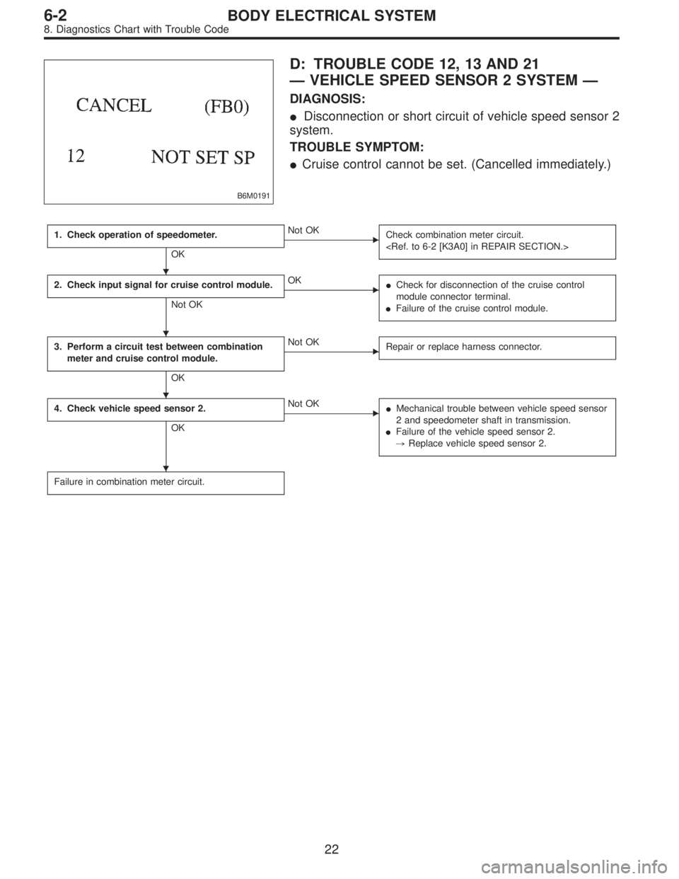
B6M0191
D: TROUBLE CODE 12, 13 AND 21
—VEHICLE SPEED SENSOR 2 SYSTEM—
DIAGNOSIS:
�Disconnection or short circuit of vehicle speed sensor 2
system.
TROUBLE SYMPTOM:
�Cruise control cannot be set. (Cancelled immediately.)
1. Check operation of speedometer.
OK
�Not OK
Check combination meter circuit.
2. Check input signal for cruise control module.
Not OK
�OK
�Check for disconnection of the cruise control
module connector terminal.
�Failure of the cruise control module.
3. Perform a circuit test between combination
meter and cruise control module.
OK
�Not OK
Repair or replace harness connector.
4. Check vehicle speed sensor 2.
OK
�Not OK
�Mechanical trouble between vehicle speed sensor
2 and speedometer shaft in transmission.
�Failure of the vehicle speed sensor 2.
,Replace vehicle speed sensor 2.
Failure in combination meter circuit.
�
�
�
�
22
6-2BODY ELECTRICAL SYSTEM
8. Diagnostics Chart with Trouble Code