Page 900 of 2890
G3M0424
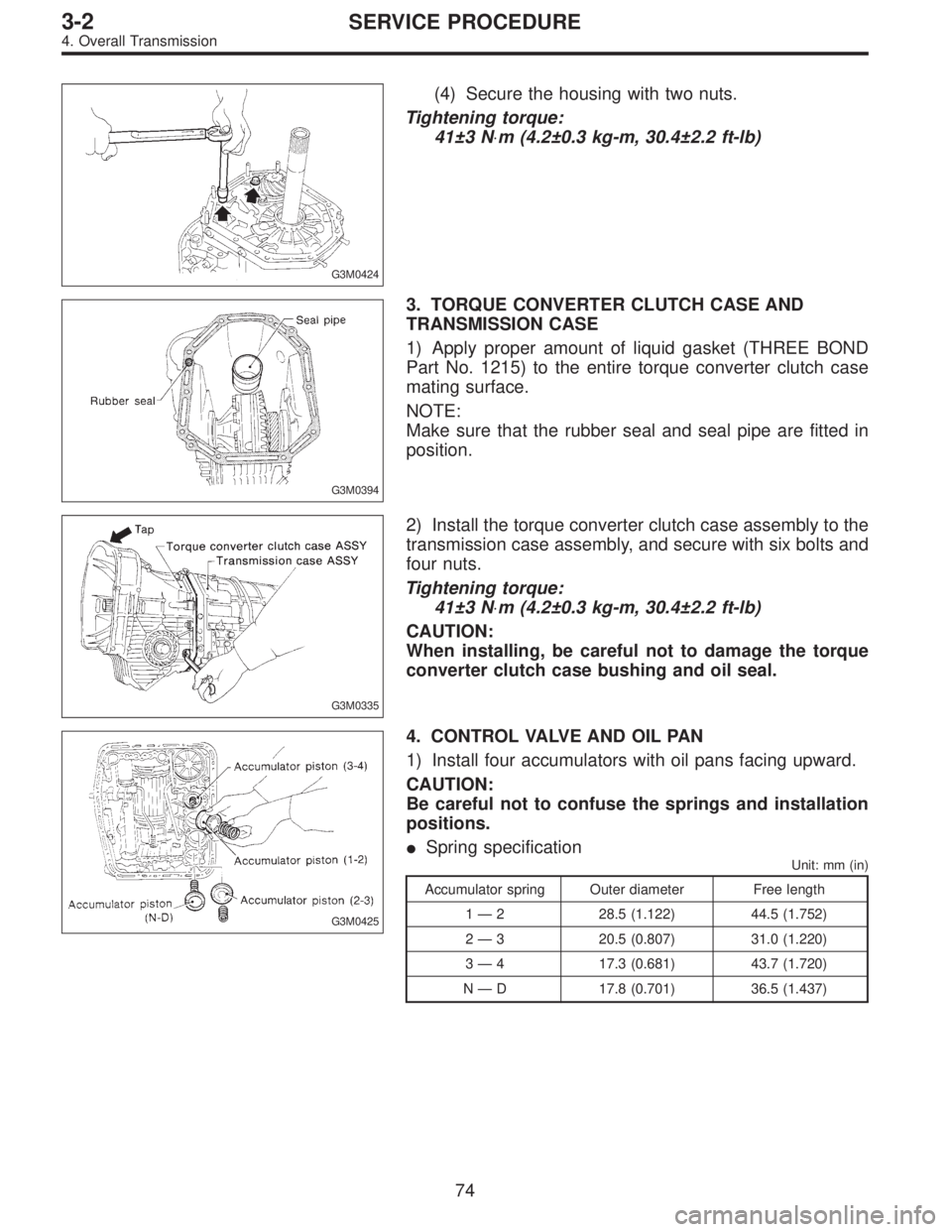
(4) Secure the housing with two nuts.
Tightening torque:
41±3 N⋅m (4.2±0.3 kg-m, 30.4±2.2 ft-lb)
G3M0394
3. TORQUE CONVERTER CLUTCH CASE AND
TRANSMISSION CASE
1) Apply proper amount of liquid gasket (THREE BOND
Part No. 1215) to the entire torque converter clutch case
mating surface.
NOTE:
Make sure that the rubber seal and seal pipe are fitted in
position.
G3M0335
2) Install the torque converter clutch case assembly to the
transmission case assembly, and secure with six bolts and
four nuts.
Tightening torque:
41±3 N⋅m (4.2±0.3 kg-m, 30.4±2.2 ft-lb)
CAUTION:
When installing, be careful not to damage the torque
converter clutch case bushing and oil seal.
G3M0425
4. CONTROL VALVE AND OIL PAN
1) Install four accumulators with oil pans facing upward.
CAUTION:
Be careful not to confuse the springs and installation
positions.
�Spring specification
Unit: mm (in)
Accumulator spring Outer diameter Free length
1—2 28.5 (1.122) 44.5 (1.752)
2—3 20.5 (0.807) 31.0 (1.220)
3—4 17.3 (0.681) 43.7 (1.720)
N—D 17.8 (0.701) 36.5 (1.437)
74
3-2SERVICE PROCEDURE
4. Overall Transmission
Page 935 of 2890
B3M0407A
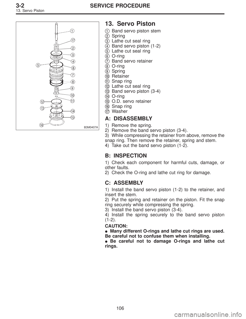
13. Servo Piston
�1Band servo piston stem
�
2Spring
�
3Lathe cut seal ring
�
4Band servo piston (1-2)
�
5Lathe cut seal ring
�
6O-ring
�
7Band servo retainer
�
8O-ring
�
9Spring
�
10Retainer
�
11Snap ring
�
12Lathe cut seal ring
�
13Band servo piston (3-4)
�
14O-ring
�
15O.D. servo retainer
�
16Snap ring
�
17Washer
A: DISASSEMBLY
1) Remove the spring.
2) Remove the band servo piston (3-4).
3) While compressing the retainer from above, remove the
snap ring. Then remove the retainer, spring and stem.
4) Take out the band servo piston (1-2).
B: INSPECTION
1) Check each component for harmful cuts, damage, or
other faults.
2) Check the O-ring and lathe cut ring for damage.
C: ASSEMBLY
1) Install the band servo piston (1-2) to the retainer, and
insert the stem.
2) Put the spring and retainer on the piston. Fit the snap
ring securely while compressing the spring.
3) Install the band servo piston (3-4).
4) Install the spring securely to the band servo piston
(1-2).
CAUTION:
�Many different O-rings and lathe cut rings are used.
Be careful not to confuse them when installing.
�Be careful not to damage O-rings and lathe cut
rings.
106
3-2SERVICE PROCEDURE
13. Servo Piston
Page 996 of 2890
G3M1050
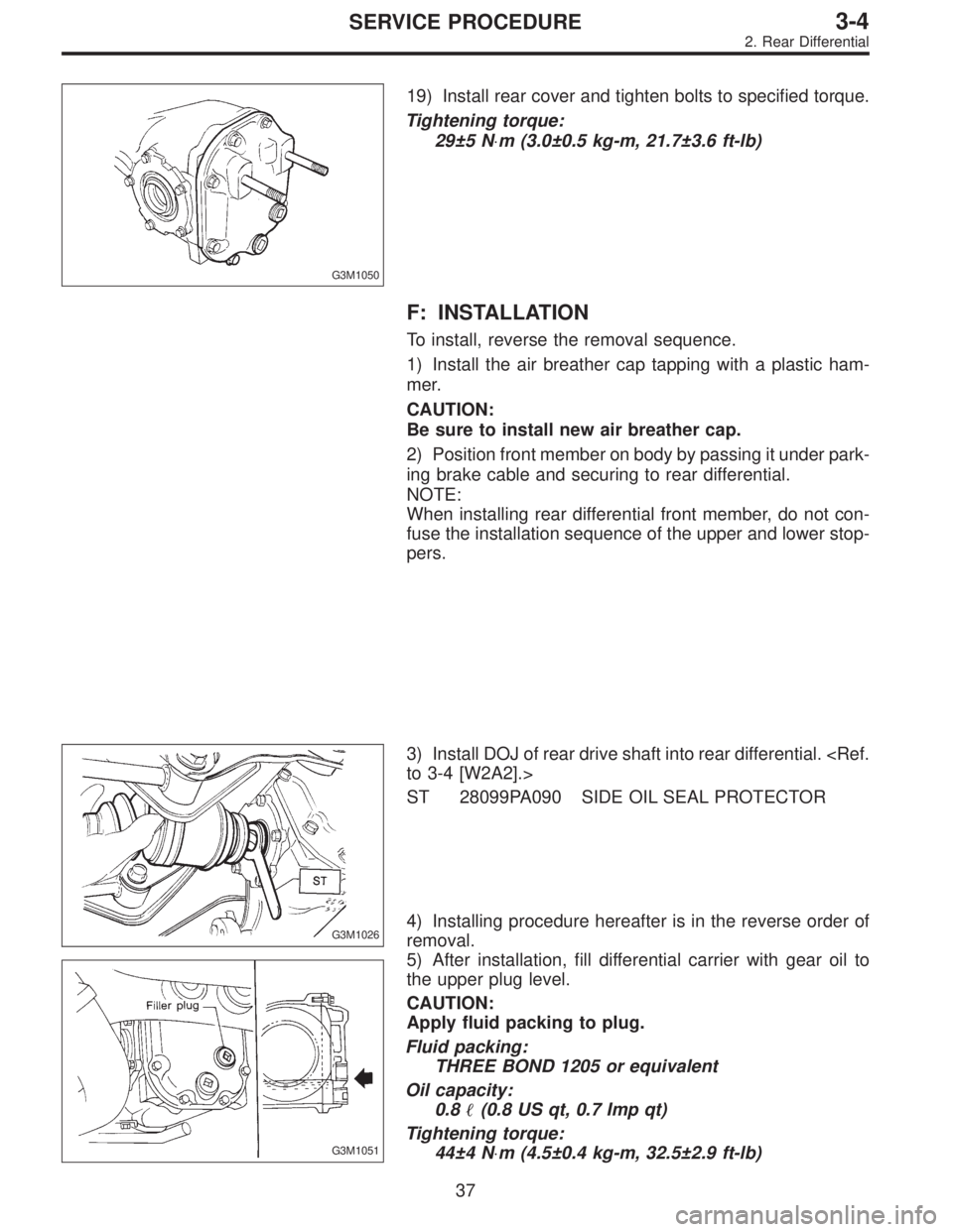
19) Install rear cover and tighten bolts to specified torque.
Tightening torque:
29±5 N⋅m (3.0±0.5 kg-m, 21.7±3.6 ft-lb)
F: INSTALLATION
To install, reverse the removal sequence.
1) Install the air breather cap tapping with a plastic ham-
mer.
CAUTION:
Be sure to install new air breather cap.
2) Position front member on body by passing it under park-
ing brake cable and securing to rear differential.
NOTE:
When installing rear differential front member, do not con-
fuse the installation sequence of the upper and lower stop-
pers.
G3M1026
3) Install DOJ of rear drive shaft into rear differential.
to 3-4 [W2A2].>
ST 28099PA090 SIDE OIL SEAL PROTECTOR
G3M1051
4) Installing procedure hereafter is in the reverse order of
removal.
5) After installation, fill differential carrier with gear oil to
the upper plug level.
CAUTION:
Apply fluid packing to plug.
Fluid packing:
THREE BOND 1205 or equivalent
Oil capacity:
0.8�(0.8 US qt, 0.7 Imp qt)
Tightening torque:
44±4 N⋅m (4.5±0.4 kg-m, 32.5±2.9 ft-lb)
37
3-4SERVICE PROCEDURE
2. Rear Differential
Page 998 of 2890
G3M1029
B: INSTALLATION
To install, reverse the removal sequence.
1) Position front member on body by passing it under park-
ing brake cable and securing to rear differential.
G3M0101
NOTE:
When installing rear differential front member, do not con-
fuse the installation sequence of the stopper.
G3M1026
2) Insert DOJ of rear drive shaft into rear differential.
ST 28099PA090 SIDE OIL SEAL PROTECTOR
CAUTION:
Before inserting, replace the differential side oil seal
and the circlip at the end of the spline shaft with a new
one.
3) Installing procedure hereafter is in the reverse order of
removal.
39
3-4SERVICE PROCEDURE
3. Rear Differential Front Member
Page 1080 of 2890
G4M0995
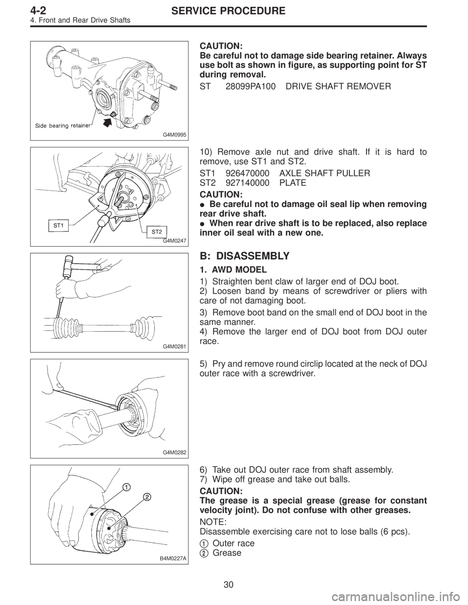
CAUTION:
Be careful not to damage side bearing retainer. Always
use bolt as shown in figure, as supporting point for ST
during removal.
ST 28099PA100 DRIVE SHAFT REMOVER
G4M0247
10) Remove axle nut and drive shaft. If it is hard to
remove, use ST1 and ST2.
ST1 926470000 AXLE SHAFT PULLER
ST2 927140000 PLATE
CAUTION:
�Be careful not to damage oil seal lip when removing
rear drive shaft.
�When rear drive shaft is to be replaced, also replace
inner oil seal with a new one.
G4M0281
B: DISASSEMBLY
1. AWD MODEL
1) Straighten bent claw of larger end of DOJ boot.
2) Loosen band by means of screwdriver or pliers with
care of not damaging boot.
3) Remove boot band on the small end of DOJ boot in the
same manner.
4) Remove the larger end of DOJ boot from DOJ outer
race.
G4M0282
5) Pry and remove round circlip located at the neck of DOJ
outer race with a screwdriver.
B4M0227A
6) Take out DOJ outer race from shaft assembly.
7) Wipe off grease and take out balls.
CAUTION:
The grease is a special grease (grease for constant
velocity joint). Do not confuse with other greases.
NOTE:
Disassemble exercising care not to lose balls (6 pcs).
�
1Outer race
�
2Grease
30
4-2SERVICE PROCEDURE
4. Front and Rear Drive Shafts
Page 1081 of 2890
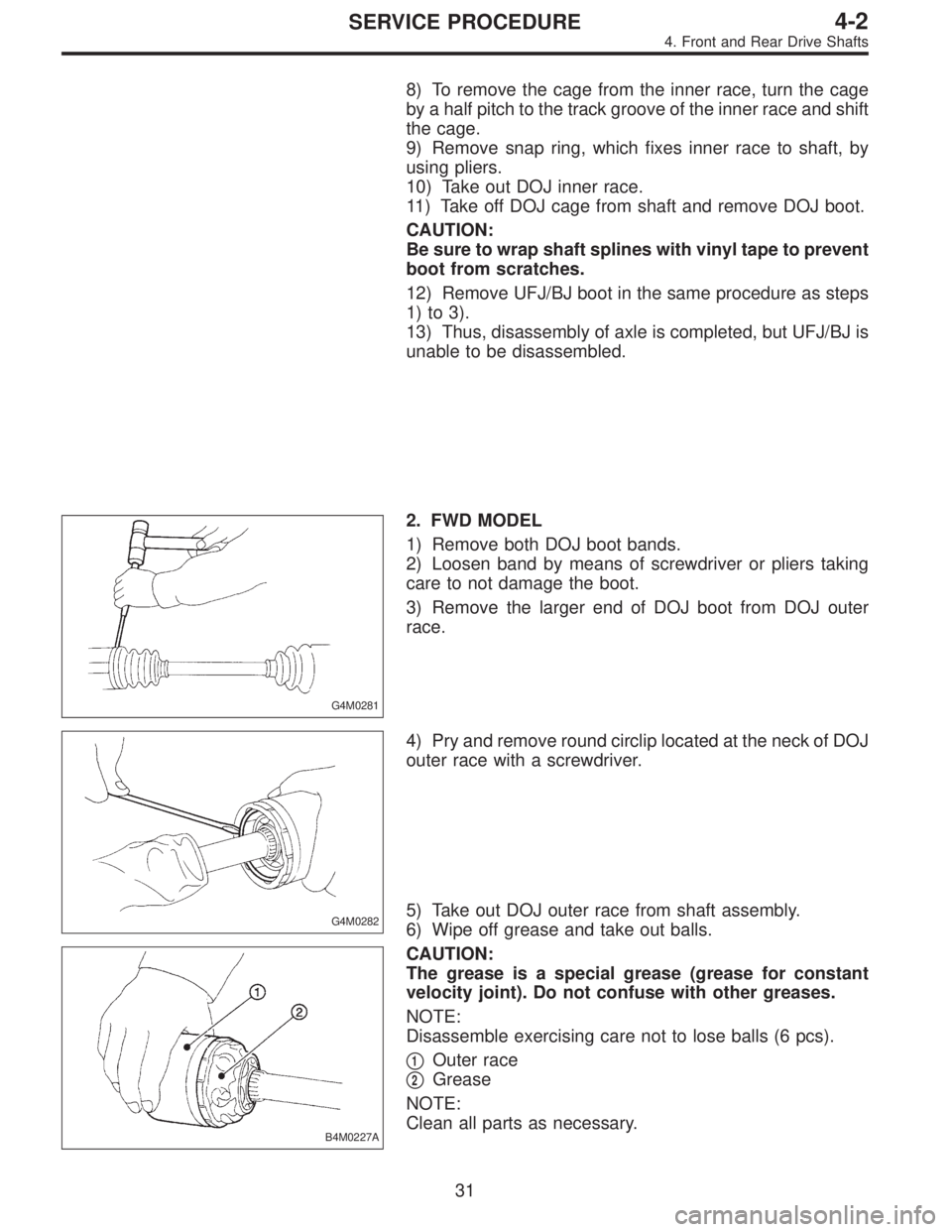
8) To remove the cage from the inner race, turn the cage
by a half pitch to the track groove of the inner race and shift
the cage.
9) Remove snap ring, which fixes inner race to shaft, by
using pliers.
10) Take out DOJ inner race.
11) Take off DOJ cage from shaft and remove DOJ boot.
CAUTION:
Be sure to wrap shaft splines with vinyl tape to prevent
boot from scratches.
12) Remove UFJ/BJ boot in the same procedure as steps
1) to 3).
13) Thus, disassembly of axle is completed, but UFJ/BJ is
unable to be disassembled.
G4M0281
2. FWD MODEL
1) Remove both DOJ boot bands.
2) Loosen band by means of screwdriver or pliers taking
care to not damage the boot.
3) Remove the larger end of DOJ boot from DOJ outer
race.
G4M0282
4) Pry and remove round circlip located at the neck of DOJ
outer race with a screwdriver.
B4M0227A
5) Take out DOJ outer race from shaft assembly.
6) Wipe off grease and take out balls.
CAUTION:
The grease is a special grease (grease for constant
velocity joint). Do not confuse with other greases.
NOTE:
Disassemble exercising care not to lose balls (6 pcs).
�
1Outer race
�
2Grease
NOTE:
Clean all parts as necessary.
31
4-2SERVICE PROCEDURE
4. Front and Rear Drive Shafts
Page 1083 of 2890
B4M0774
3. FTJ (Free-ring Tripod Joint)
1) Place alignment marks on shaft and outer race.
B4M0775A
2) Remove FTJ boot band and boot.
CAUTION:
Be careful not to damage boot.
B4M0776
3) Remove circlip from FTJ outer race using screwdriver.
4) Remove FTJ outer race from shaft assembly.
5) Wipe off grease.
CAUTION:
The grease is a special grease. Do not confuse with
other greases.
B4M0777
6) Place alignment mark on free ring and trunnion.
7) Remove free ring from trunnion.
33
4-2SERVICE PROCEDURE
4. Front and Rear Drive Shafts
Page 1251 of 2890
2) Installation is in reverse order of removal.
CAUTION:
�Use new retainers and clinch them when installing
brake shoes to levers.
�Ensure that parking lever moves smoothly.
�Do not confuse left parking lever with right one.
�Do not confuse left strut with right one.
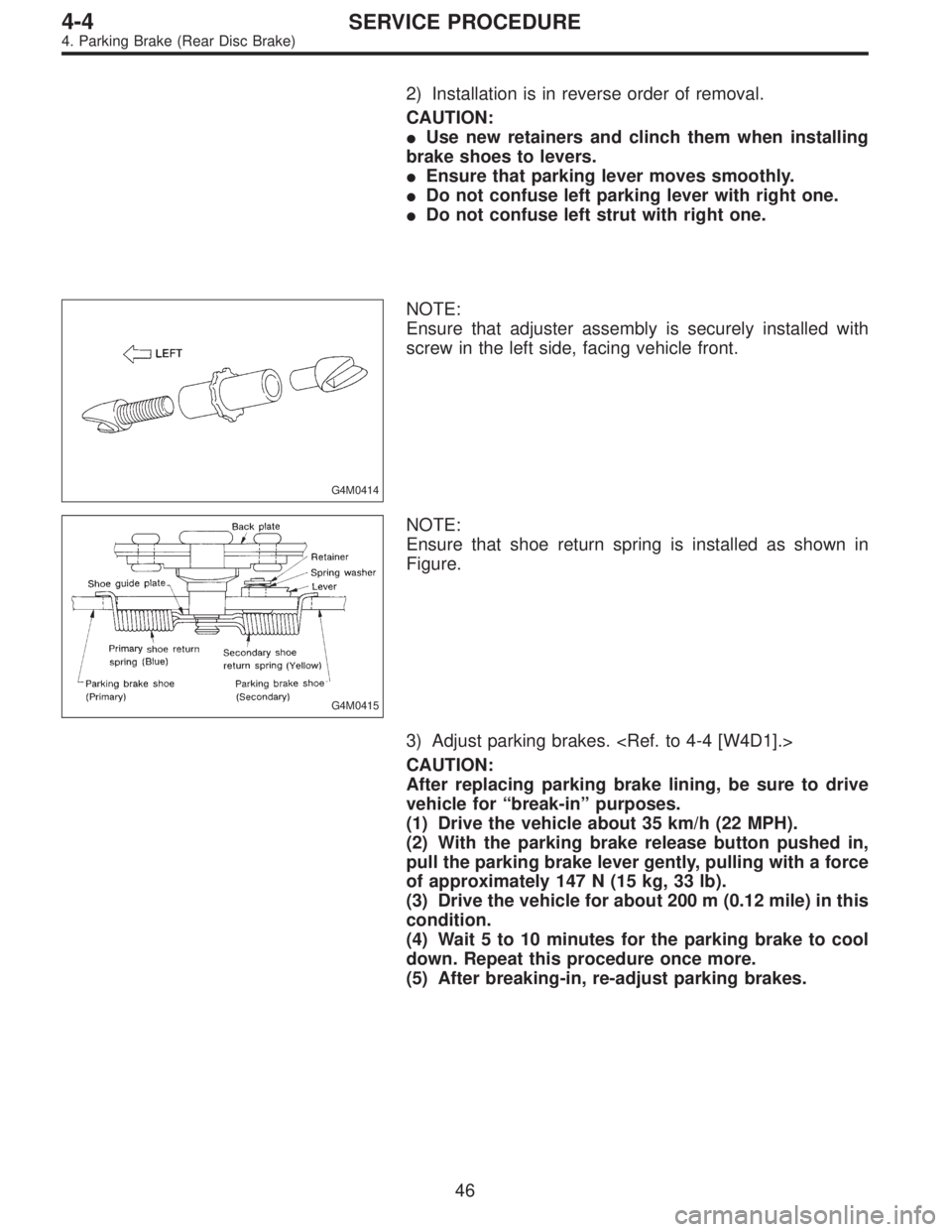
G4M0414
NOTE:
Ensure that adjuster assembly is securely installed with
screw in the left side, facing vehicle front.
G4M0415
NOTE:
Ensure that shoe return spring is installed as shown in
Figure.
3) Adjust parking brakes.
CAUTION:
After replacing parking brake lining, be sure to drive
vehicle for“break-in”purposes.
(1) Drive the vehicle about 35 km/h (22 MPH).
(2) With the parking brake release button pushed in,
pull the parking brake lever gently, pulling with a force
of approximately 147 N (15 kg, 33 lb).
(3) Drive the vehicle for about 200 m (0.12 mile) in this
condition.
(4) Wait 5 to 10 minutes for the parking brake to cool
down. Repeat this procedure once more.
(5) After breaking-in, re-adjust parking brakes.
46
4-4SERVICE PROCEDURE
4. Parking Brake (Rear Disc Brake)