Page 1860 of 2890
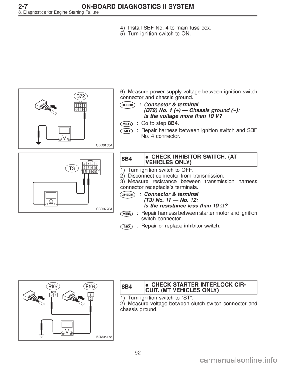
4) Install SBF No. 4 to main fuse box.
5) Turn ignition switch to ON.
OBD0103A
6) Measure power supply voltage between ignition switch
connector and chassis ground.
: Connector & terminal
(B72) No. 1 (+)—Chassis ground (�):
Is the voltage more than 10 V?
: Go to step8B4.
: Repair harness between ignition switch and SBF
No. 4 connector.
OBD0726A
8B4�CHECK INHIBITOR SWITCH. (AT
VEHICLES ONLY)
1) Turn ignition switch to OFF.
2) Disconnect connector from transmission.
3) Measure resistance between transmission harness
connector receptacle’s terminals.
: Connector & terminal
(T3) No. 11—No. 12:
Is the resistance less than 10Ω?
: Repair harness between starter motor and ignition
switch connector.
: Repair or replace inhibitor switch.
B2M0517A
8B4�CHECK STARTER INTERLOCK CIR-
CUIT. (MT VEHICLES ONLY)
1) Turn ignition switch to“ST”.
2) Measure voltage between clutch switch connector and
chassis ground.
92
2-7ON-BOARD DIAGNOSTICS II SYSTEM
8. Diagnostics for Engine Starting Failure
Page 2122 of 2890
10BQ2
CHECK POWER SUPPLY FOR RELAYS.
Turn ignition switch to OFF.
: Is the fuse in power supply circuit broken?
: Replace the fuse.
: Go to step10BQ3.
OBD0535
10BQ3CHECK MAIN FAN RELAY 1, SUB FAN
RELAY 1 AND MAIN FAN RELAY.
1) Remove main fan relay 1. (With A/C models only)
2) Measure resistance between main fan relay 1 termi-
nals.
: Terminal
No. 1—No. 3:
Is the resistance between 87 and 107Ω?
: Go to next step 3).
: Replace main fan relay 1.
OBD0536
3) Remove sub fan relay 1. (With A/C models only)
Remove main fan relay. (Without A/C models only)
4) Measure resistance between sub fan relay 1 or main
fan relay terminals.
: Terminal
No. 1—No. 3:
Is the resistance between 83 and 117Ω?
: Go to step10BQ4.
: Replace sub fan relay 1.
354
2-7ON-BOARD DIAGNOSTICS II SYSTEM
10. Diagnostics Chart with Trouble Code
Page 2149 of 2890
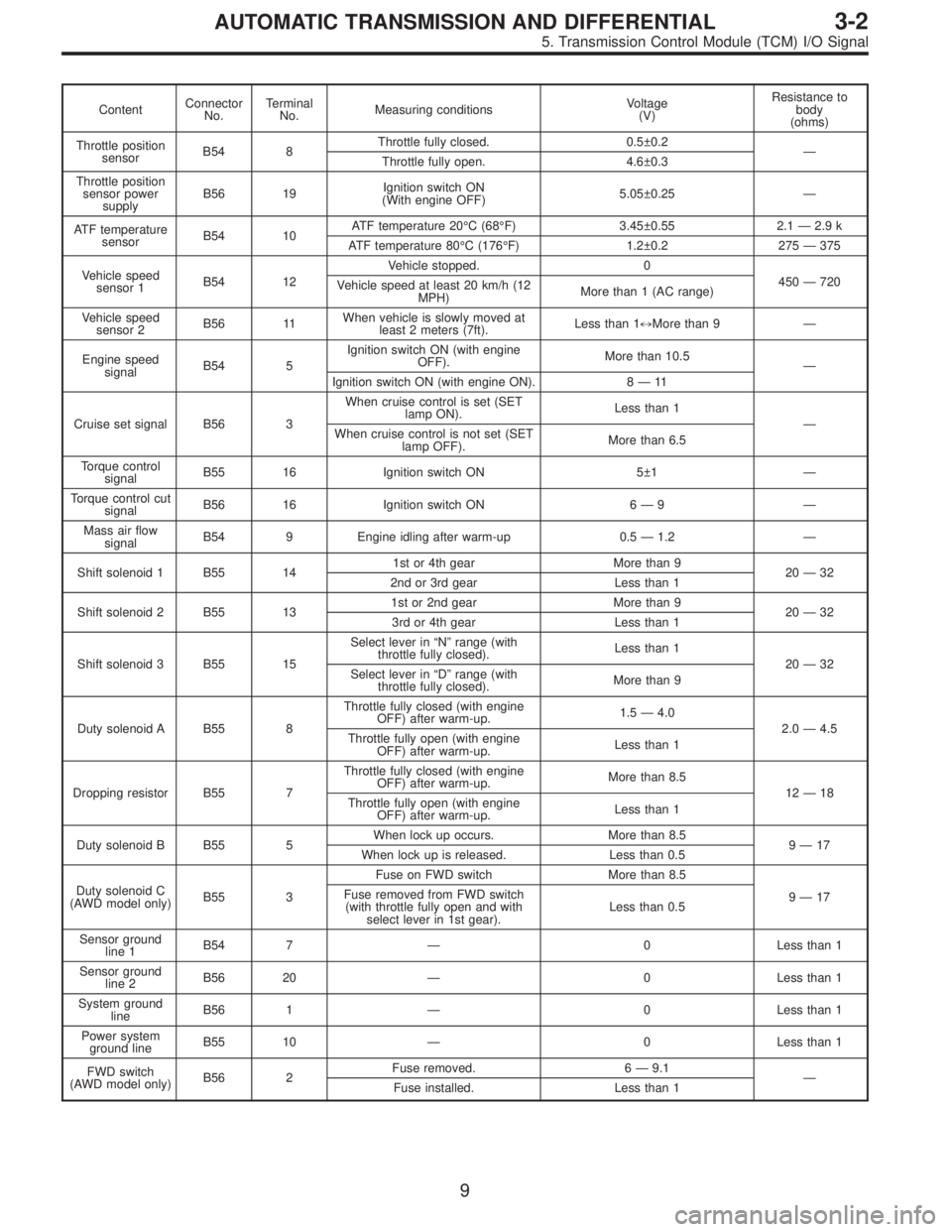
ContentConnector
No.Terminal
No.Measuring conditionsVoltage
(V)Resistance to
body
(ohms)
Throttle position
sensorB54 8Throttle fully closed. 0.5±0.2
—
Throttle fully open. 4.6±0.3
Throttle position
sensor power
supplyB56 19Ignition switch ON
(With engine OFF)5.05±0.25—
ATF temperature
sensorB54 10ATF temperature 20°C(68°F) 3.45±0.55 2.1—2.9 k
ATF temperature 80°C (176°F) 1.2±0.2 275—375
Vehicle speed
sensor 1B54 12Vehicle stopped. 0
450—720
Vehicle speed at least 20 km/h (12
MPH)More than 1 (AC range)
Vehicle speed
sensor 2B56 11When vehicle is slowly moved at
least 2 meters (7ft).Less than 1)More than 9—
Engine speed
signalB54 5Ignition switch ON (with engine
OFF).More than 10.5
—
Ignition switch ON (with engine ON). 8—11
Cruise set signal B56 3When cruise control is set (SET
lamp ON).Less than 1
—
When cruise control is not set (SET
lamp OFF).More than 6.5
Torque control
signalB55 16 Ignition switch ON 5±1—
Torque control cut
signalB56 16 Ignition switch ON 6—9—
Mass air flow
signalB54 9 Engine idling after warm-up 0.5—1.2—
Shift solenoid 1 B55 141st or 4th gear More than 9
20—32
2nd or 3rd gear Less than 1
Shift solenoid 2 B55 131st or 2nd gear More than 9
20—32
3rd or 4th gear Less than 1
Shift solenoid 3 B55 15Select lever in“N”range (with
throttle fully closed).Less than 1
20—32
Select lever in“D”range (with
throttle fully closed).More than 9
Duty solenoid A B55 8Throttle fully closed (with engine
OFF) after warm-up.1.5—4.0
2.0—4.5
Throttle fully open (with engine
OFF) after warm-up.Less than 1
Dropping resistor B55 7Throttle fully closed (with engine
OFF) after warm-up.More than 8.5
12—18
Throttle fully open (with engine
OFF) after warm-up.Less than 1
Duty solenoid B B55 5When lock up occurs. More than 8.5
9—17
When lock up is released. Less than 0.5
Duty solenoid C
(AWD model only)B55 3Fuse on FWD switch More than 8.5
9—17 Fuse removed from FWD switch
(with throttle fully open and with
select lever in 1st gear).Less than 0.5
Sensor ground
line 1B54 7—0 Less than 1
Sensor ground
line 2B56 20—0 Less than 1
System ground
lineB56 1—0 Less than 1
Power system
ground lineB55 10—0 Less than 1
FWD switch
(AWD model only)B56 2Fuse removed. 6—9.1
—
Fuse installed. Less than 1
9
3-2AUTOMATIC TRANSMISSION AND DIFFERENTIAL
5. Transmission Control Module (TCM) I/O Signal
Page 2154 of 2890
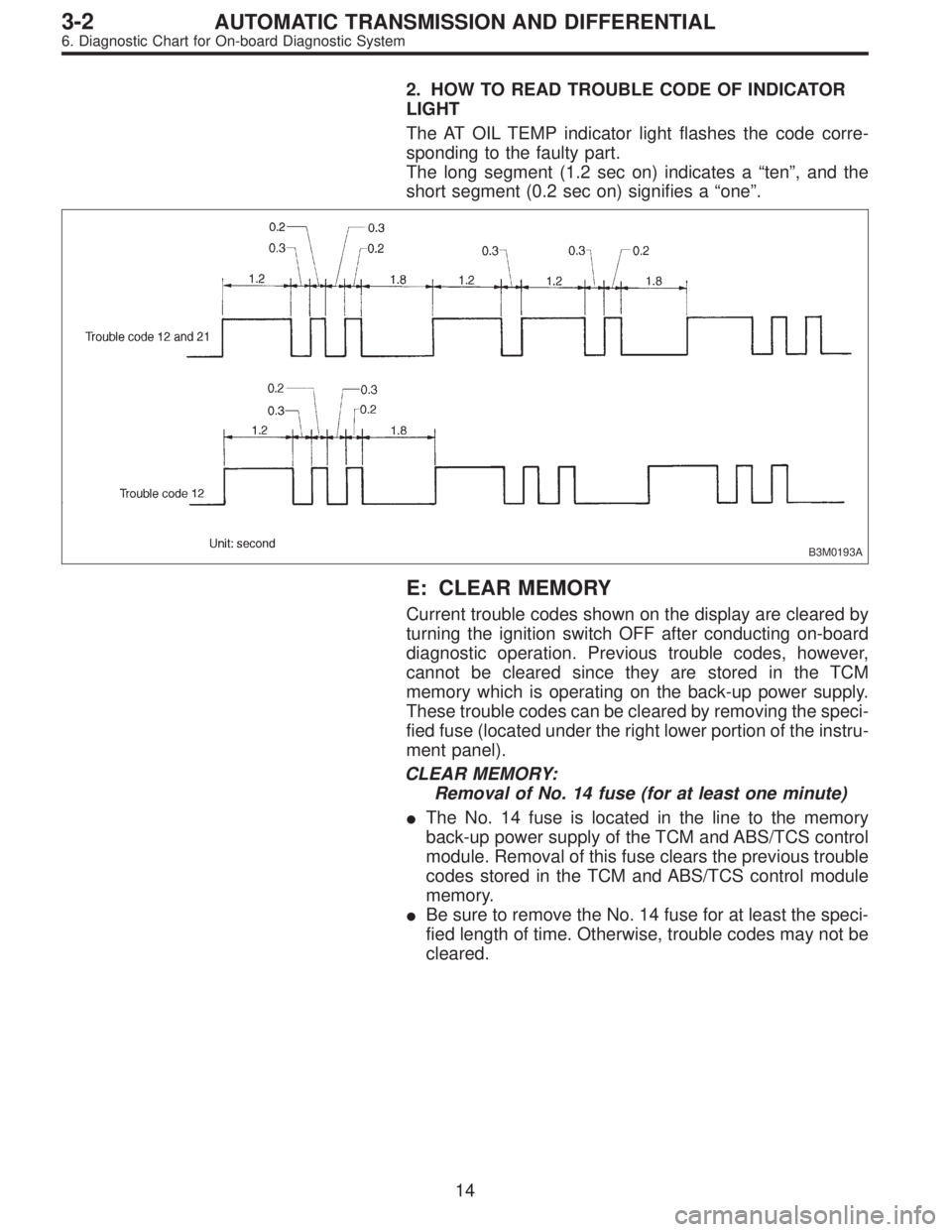
2. HOW TO READ TROUBLE CODE OF INDICATOR
LIGHT
The AT OIL TEMP indicator light flashes the code corre-
sponding to the faulty part.
The long segment (1.2 sec on) indicates a“ten”, and the
short segment (0.2 sec on) signifies a“one”.
B3M0193A
E: CLEAR MEMORY
Current trouble codes shown on the display are cleared by
turning the ignition switch OFF after conducting on-board
diagnostic operation. Previous trouble codes, however,
cannot be cleared since they are stored in the TCM
memory which is operating on the back-up power supply.
These trouble codes can be cleared by removing the speci-
fied fuse (located under the right lower portion of the instru-
ment panel).
CLEAR MEMORY:
Removal of No. 14 fuse (for at least one minute)
�The No. 14 fuse is located in the line to the memory
back-up power supply of the TCM and ABS/TCS control
module. Removal of this fuse clears the previous trouble
codes stored in the TCM and ABS/TCS control module
memory.
�Be sure to remove the No. 14 fuse for at least the speci-
fied length of time. Otherwise, trouble codes may not be
cleared.
14
3-2AUTOMATIC TRANSMISSION AND DIFFERENTIAL
6. Diagnostic Chart for On-board Diagnostic System
Page 2195 of 2890
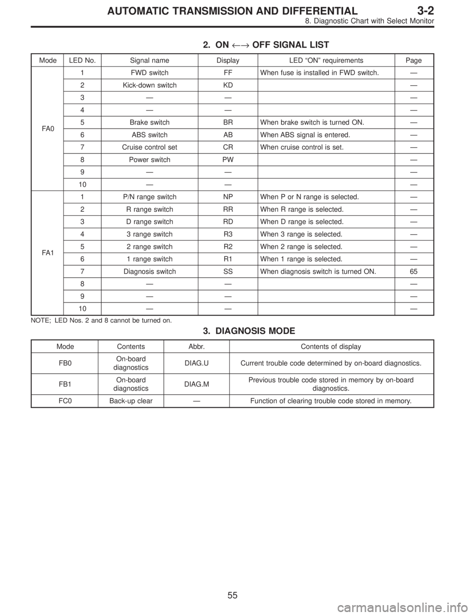
2. ON←→OFF SIGNAL LIST
Mode LED No. Signal name Display LED“ON”requirements Page
FA 01 FWD switch FF When fuse is installed in FWD switch.—
2 Kick-down switch KD—
3—— —
4—— —
5 Brake switch BR When brake switch is turned ON.—
6 ABS switch AB When ABS signal is entered.—
7 Cruise control set CR When cruise control is set.—
8 Power switch PW—
9—— —
10—— —
FA 11 P/N range switch NP When P or N range is selected.—
2 R range switch RR When R range is selected.—
3 D range switch RD When D range is selected.—
4 3 range switch R3 When 3 range is selected.—
5 2 range switch R2 When 2 range is selected.—
6 1 range switch R1 When 1 range is selected.—
7 Diagnosis switch SS When diagnosis switch is turned ON. 65
8—— —
9—— —
10—— —
NOTE; LED Nos. 2 and 8 cannot be turned on.
3. DIAGNOSIS MODE
Mode Contents Abbr. Contents of display
FB0On-board
diagnosticsDIAG.U Current trouble code determined by on-board diagnostics.
FB1On-board
diagnosticsDIAG.MPrevious trouble code stored in memory by on-board
diagnostics.
FC0 Back-up clear—Function of clearing trouble code stored in memory.
55
3-2AUTOMATIC TRANSMISSION AND DIFFERENTIAL
8. Diagnostic Chart with Select Monitor
Page 2204 of 2890
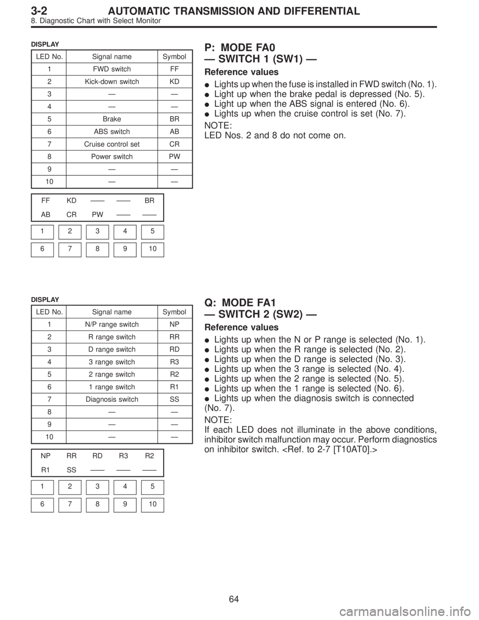
DISPLAY
LED No. Signal name Symbol
1 FWD switch FF
2 Kick-down switch KD
3——
4——
5 Brake BR
6 ABS switch AB
7 Cruise control set CR
8 Power switch PW
9——
10——
FF KD—— ——BR
AB CR PW—— ——
1
2345
678910
P: MODE FA0
—SWITCH 1 (SW1)—
Reference values
�Lights up when the fuse is installed in FWD switch (No. 1).
�Light up when the brake pedal is depressed (No. 5).
�Light up when the ABS signal is entered (No. 6).
�Lights up when the cruise control is set (No. 7).
NOTE:
LED Nos. 2 and 8 do not come on.
DISPLAY
LED No. Signal name Symbol
1 N/P range switch NP
2 R range switch RR
3 D range switch RD
4 3 range switch R3
5 2 range switch R2
6 1 range switch R1
7 Diagnosis switch SS
8——
9——
10——
NP RR RD R3 R2
R1 SS—— —— ——
1
2345
678910
Q: MODE FA1
—SWITCH 2 (SW2)—
Reference values
�Lights up when the N or P range is selected (No. 1).
�Lights up when the R range is selected (No. 2).
�Lights up when the D range is selected (No. 3).
�Lights up when the 3 range is selected (No. 4).
�Lights up when the 2 range is selected (No. 5).
�Lights up when the 1 range is selected (No. 6).
�Lights up when the diagnosis switch is connected
(No. 7).
NOTE:
If each LED does not illuminate in the above conditions,
inhibitor switch malfunction may occur. Perform diagnostics
on inhibitor switch.
64
3-2AUTOMATIC TRANSMISSION AND DIFFERENTIAL
8. Diagnostic Chart with Select Monitor
Page 2212 of 2890
1. Supplemental Restraint System
“Airbag”
Airbag system wiring harness is routed near the ABS/TCS
control module, ABS sensor and hydraulic control unit.
CAUTION:
�All Airbag system wiring harness and connectors
are colored yellow. Do not use electrical test equip-
ment on these circuit.
�Be careful not to damage Airbag system wiring har-
ness when servicing the ABS/TCS control module,
ABS sensor and hydraulic control unit.
2. Pre-inspection
Before performing diagnostics, check the following items
which might affect ABS/TCS problems:
A: MECHANICAL INSPECTION
1. POWER SUPPLY
1) Measure battery voltage and specific gravity of electro-
lyte.
Standard voltage: 12 V, or more
Specific gravity: Above 1.260
2) Check the condition of the main and other fuses, and
harnesses and connectors. Also check for proper ground-
ing.
2. BRAKE FLUID
1) Check brake fluid level.
2) Check brake fluid leakage.
3. BRAKE DRAG
Check brake drag.
4. BRAKE PAD AND ROTOR
Check brake pad and rotor.
5. TIRE SPECIFICATIONS, TIRE WEAR AND AIR
PRESSURE
Check tire specifications, tire wear and air pressure.
to 4-2 [S1A0].>
2
4-4bBRAKES
1. Supplemental Restraint System“Airbag”- 2. Pre-inspection
Page 2213 of 2890
1. Supplemental Restraint System
“Airbag”
Airbag system wiring harness is routed near the ABS/TCS
control module, ABS sensor and hydraulic control unit.
CAUTION:
�All Airbag system wiring harness and connectors
are colored yellow. Do not use electrical test equip-
ment on these circuit.
�Be careful not to damage Airbag system wiring har-
ness when servicing the ABS/TCS control module,
ABS sensor and hydraulic control unit.
2. Pre-inspection
Before performing diagnostics, check the following items
which might affect ABS/TCS problems:
A: MECHANICAL INSPECTION
1. POWER SUPPLY
1) Measure battery voltage and specific gravity of electro-
lyte.
Standard voltage: 12 V, or more
Specific gravity: Above 1.260
2) Check the condition of the main and other fuses, and
harnesses and connectors. Also check for proper ground-
ing.
2. BRAKE FLUID
1) Check brake fluid level.
2) Check brake fluid leakage.
3. BRAKE DRAG
Check brake drag.
4. BRAKE PAD AND ROTOR
Check brake pad and rotor.
5. TIRE SPECIFICATIONS, TIRE WEAR AND AIR
PRESSURE
Check tire specifications, tire wear and air pressure.
to 4-2 [S1A0].>
2
4-4bBRAKES
1. Supplemental Restraint System“Airbag”- 2. Pre-inspection