Page 1284 of 2890
 In the case of AWD vehicles, install a spare fuse with
the FWD connector in the engine compartment to simulate
FWD vehicles.
B4M0082A
2) Con")
G4M0462
3. CHECKING THE HYDRAULIC UNIT WITH BRAKE
TESTER
1) In the case of AWD vehicles, install a spare fuse with
the FWD connector in the engine compartment to simulate
FWD vehicles.
B4M0082A
2) Connect diagnosis terminals to 3 terminals (K) and 6
terminals (L) of the diagnosis connector beside driver seat
heater unit.
G4M0464
3) Set the front wheels or rear wheels on the brake tester
and set the select lever’s position at“neutral”.
4) Operate the brake tester.
5) Perform sequence control.
(1) Turn ignition switch ON.
(2) The ABS warning light comes on.
(3) Depress the brake pedal within 0.5 seconds after
the warning light goes out so that the brake tester reg-
isters a pressure equal to the initial value.
CAUTION:
Do not depress the clutch pedal.
NOTE:
The engine must not be operating.
6) Hydraulic unit begins to work; and check the following
working sequence.
(1) The left front wheel performs decompression,
holding, and compression in sequence, and subse-
quently the right front wheel repeats the cycle.
(2) Simultaneously both right and left rear wheel per-
form decompression, holding, and compression in
sequence.
77
4-4SERVICE PROCEDURE
15. Hydraulic Unit for ABS System (Except ABS 5.3 Type)
Page 1285 of 2890
 Read values indicated on the brake tester and check if
the fluctuation of values, when decompressed and
compressed, meet the standard values.
Initial value When decompressed When compressed
Front w")
7) Read values indicated on the brake tester and check if
the fluctuation of values, when decompressed and
compressed, meet the standard values.
Initial value When decompressed When compressed
Front wheel 1,961 N (200 kg, 441 lb) 245 N (25 kg, 55 lb) 1,961 N (200 kg, 441 lb)
Rear wheel 686 N (70 kg, 154 lb) 245 N (25 kg, 55 lb) 686 N (70 kg, 154 lb)
�In case of hydraulic unit plunger piston malfunction:
Initial value When decompressed When compressed
Rear right wheel 686 N (70 kg, 154 lb) 245 N (25 kg, 55 lb) 686 N (70 kg, 154 lb)
Rear left wheel 686 N (70 kg, 154 lb) 686 N (70 kg, 154 lb) 686 N (70 kg, 154 lb)
8) After checking, also check if any irregular brake pedal
tightness is felt.
9) In case of AWD vehicles, remove the spare fuse from
the FWD connector in the engine compartment to return to
the original AWD state.
C: SEQUENCE CONTROL
Under the sequence control, after the hydraulic unit sole-
noid valve is driven, the operation of the hydraulic unit can
be checked by means of the brake tester or pressure
gauge.
B4M0082A
1. OPERATIONAL GUIDELINES OF THE SEQUENCE
CONTROL
1) Connect diagnosis terminals to 3 terminals (K) and 6
terminals (L) of the diagnosis connector beside driver seat
heater unit.
2) Set the speed of all wheels at 4 km/h (2 MPH) or less.
3) Within 0.5 seconds after the ABS warning lamp goes
out, immediately after the ignition switch is turned to on,
depress the brake pedal and hold.
CAUTION:
Do not depress the clutch pedal.
NOTE:
�When the ignition switch is set to on, the brake pedal
must not be depressed.
�Engine must not operate.
78
4-4SERVICE PROCEDURE
15. Hydraulic Unit for ABS System (Except ABS 5.3 Type)
Page 1323 of 2890
 In the case of AWD AT vehicles, install a spare fuse with
the FWD connector in the engine compartment to simulate
FWD vehicles")
G4M0462
2. CHECKING THE HYDRAULIC UNIT ABS
OPERATION WITH BRAKE TESTER
1) In the case of AWD AT vehicles, install a spare fuse with
the FWD connector in the engine compartment to simulate
FWD vehicles.
2) Prepare for operating ABS sequence control.
4-4 [W22D1] or 4-4 [W22D2].>
G4M0464
3) Set the front wheels or rear wheels on the brake tester
and set the select lever’s position at“neutral”.
4) Operate the brake tester.
5) Perform ABS sequence control.
step 1 or 4-4 [W22D2] step 1.>
6) Hydraulic unit begins to work; and check the following
working sequence.
(1) The FL wheel performs decompression, holding,
and compression in sequence, and subsequently the
FR wheel repeats the cycle.
(2) The RR wheel performs decompression, holding,
and compression in sequence, and subsequently the
RL wheel repeats the cycle.
7) Read values indicated on the brake tester and check if
the fluctuation of values, when decompressed and
compressed, meet the standard values.
Unit: N (kg, lb)
Initial value When decompressed When compressed
Front wheel 981 (100, 221) 490 (50, 110) or less 981 (100, 221) or more
Rear wheel 981 (100, 221) 490 (50, 110) or less 981 (100, 221) or more
8) After checking, also check if any irregular brake pedal
tightness is felt.
11 3
4-4SERVICE PROCEDURE
22. Hydraulic Unit for ABS System (ABS 5.3 Type)
Page 1376 of 2890
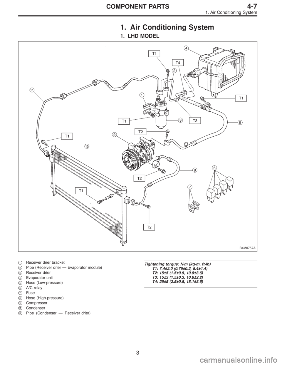
1. Air Conditioning System
1. LHD MODEL
B4M0757A
�1Receiver drier bracket
�
2Pipe (Receiver drier—Evaporator module)
�
3Receiver drier
�
4Evaporator unit
�
5Hose (Low-pressure)
�
6A/C relay
�
7Fuse
�
8Hose (High-pressure)
�
9Compressor
�
10Condenser
�
11Pipe (Condenser—Receiver drier)
Tightening torque: N⋅m (kg-m, ft-lb)
T1: 7.4±2.0 (0.75±0.2, 5.4±1.4)
T2: 15±5 (1.5±0.5, 10.8±3.6)
T3: 15±3 (1.5±0.3, 10.8±2.2)
T4: 25±5 (2.5±0.5, 18.1±3.6)
3
4-7COMPONENT PARTS
1. Air Conditioning System
Page 1377 of 2890
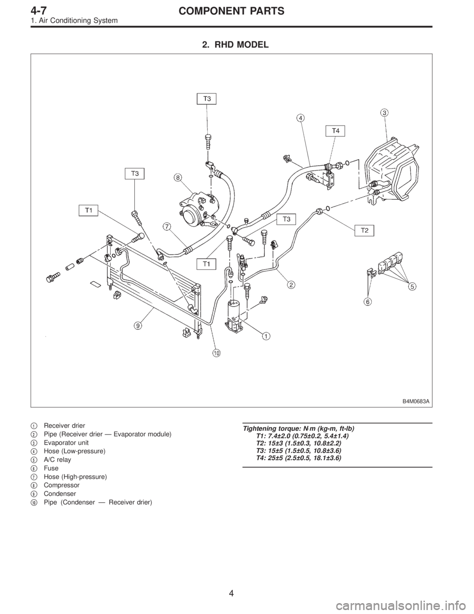
2. RHD MODEL
B4M0683A
�1Receiver drier
�
2Pipe (Receiver drier—Evaporator module)
�
3Evaporator unit
�
4Hose (Low-pressure)
�
5A/C relay
�
6Fuse
�
7Hose (High-pressure)
�
8Compressor
�
9Condenser
�
10Pipe (Condenser—Receiver drier)
Tightening torque: N⋅m (kg-m, ft-lb)
T1: 7.4±2.0 (0.75±0.2, 5.4±1.4)
T2: 15±3 (1.5±0.3, 10.8±2.2)
T3: 15±5 (1.5±0.5, 10.8±3.6)
T4: 25±5 (2.5±0.5, 18.1±3.6)
4
4-7COMPONENT PARTS
1. Air Conditioning System
Page 1415 of 2890
![SUBARU LEGACY 1996 Service Repair Manual B4M0103
B4M0764
16. Flexible Hose
A: REMOVAL AND INSTALLATION
1) Disconnect battery negative terminal.
2) Discharge refrigerant using refrigerant recovery system.
<Ref. to 4-7 [W601].>
3) Remove low-p](/manual-img/17/57433/w960_57433-1414.png "SUBARU LEGACY 1996 Service Repair Manual B4M0103
B4M0764
16. Flexible Hose
A: REMOVAL AND INSTALLATION
1) Disconnect battery negative terminal.
2) Discharge refrigerant using refrigerant recovery system.
<Ref. to 4-7 [W601].>
3) Remove low-p")
B4M0103
B4M0764
16. Flexible Hose
A: REMOVAL AND INSTALLATION
1) Disconnect battery negative terminal.
2) Discharge refrigerant using refrigerant recovery system.
3) Remove low-pressure hose.
(1) Remove hose attaching bolts.
CAUTION:
Plug the opening to prevent foreign matter from get-
ting in.
(2) Disconnect the connector at evaporator module.
4) Remove high-pressure hose.
(1) Disconnect hose attaching bolt (compressor side).
(2) Disconnect hose attaching bolt (condenser side).
CAUTION:
Plug the opening to prevent foreign matter from get-
ting in.
5) Installation is in the reverse order of removal.
6) Charge refrigerant.
G4M0649
17. Relay and Fuse
A: LOCATION
Relays used with A/C system are located as shown in fig-
ure.
1) A/C relay
2) Main fan (radiator fan) relay
3) Sub fan (condenser fan) relay
4) Sub fan (condenser fan) water temperature relay
5) Fuses (10 A and 20 A)
G4M0651
B: INSPECTION
1) Check conduction with a circuit tester (ohm range)
according to the following table in figure.
B4M0105A
2) Replace relays which do not meet specifications.
39
4-7SERVICE PROCEDURE
16. Flexible Hose - 17. Relay and Fuse
Page 1416 of 2890
![SUBARU LEGACY 1996 Service Repair Manual B4M0103
B4M0764
16. Flexible Hose
A: REMOVAL AND INSTALLATION
1) Disconnect battery negative terminal.
2) Discharge refrigerant using refrigerant recovery system.
<Ref. to 4-7 [W601].>
3) Remove low-p](/manual-img/17/57433/w960_57433-1415.png "SUBARU LEGACY 1996 Service Repair Manual B4M0103
B4M0764
16. Flexible Hose
A: REMOVAL AND INSTALLATION
1) Disconnect battery negative terminal.
2) Discharge refrigerant using refrigerant recovery system.
<Ref. to 4-7 [W601].>
3) Remove low-p")
B4M0103
B4M0764
16. Flexible Hose
A: REMOVAL AND INSTALLATION
1) Disconnect battery negative terminal.
2) Discharge refrigerant using refrigerant recovery system.
3) Remove low-pressure hose.
(1) Remove hose attaching bolts.
CAUTION:
Plug the opening to prevent foreign matter from get-
ting in.
(2) Disconnect the connector at evaporator module.
4) Remove high-pressure hose.
(1) Disconnect hose attaching bolt (compressor side).
(2) Disconnect hose attaching bolt (condenser side).
CAUTION:
Plug the opening to prevent foreign matter from get-
ting in.
5) Installation is in the reverse order of removal.
6) Charge refrigerant.
G4M0649
17. Relay and Fuse
A: LOCATION
Relays used with A/C system are located as shown in fig-
ure.
1) A/C relay
2) Main fan (radiator fan) relay
3) Sub fan (condenser fan) relay
4) Sub fan (condenser fan) water temperature relay
5) Fuses (10 A and 20 A)
G4M0651
B: INSPECTION
1) Check conduction with a circuit tester (ohm range)
according to the following table in figure.
B4M0105A
2) Replace relays which do not meet specifications.
39
4-7SERVICE PROCEDURE
16. Flexible Hose - 17. Relay and Fuse
Page 1424 of 2890
5. Compressor Clutch Diagnosis
Compressor clutch is not engaged.
Check both 10 A fuse for A/C.
Fuse O.K. Fuse blown
Determine cause of blown fuse. Replace faulty part(s)
and fuse.
Does 12 volts exist in control panel connector (R/B)?
Ye s
�No
Faulty harness
Does 12 volts exist in control panel connector (B/W)?
Ye s
�No
Faulty A/C switch
Does 12 volts exist in dual pressure switch connector
(G/Y)?
Ye s
�No
Faulty harness
Does 12 volts exist in dual pressure switch connector
(Br/Y)?
Ye s
�No
Faulty dual pressure switch
Does 12 volts exist in A/C relay connector (Br/R) and
(W)?
Ye s
�No
Faulty harness
Does 12 volts exist in A/C relay connector (R/W)?
Ye s
�No
Does 0 volts exist in A/C relay connector (Br/Y)?
Ye s N o
Faulty A/C relay
To�B
Does 12 volts exist in thermoswitch connector (R/W)?
Ye s
�No
Faulty harness
Does 12 volts exist in thermoswitch connector (L/R)?
Ye s
�No
Faulty thermoswitch
To�A
�
�
�
�
�
�
�
�
��
�
�
�
47
4-7DIAGNOSTICS
5. Compressor Clutch Diagnosis

and fuse.
Does 12 volts exist")