Page 618 of 2890
 Check fuse No. 13.
2) Turn ignition switch to ACC.
3) Measure voltage between fuse and relay box, and body.
Connector & terminal / Specified voltage:
(F40)")
B2M0427A
1. CHECK FUSE AND POWER SUPPLY.
1) Check fuse No. 13.
2) Turn ignition switch to ACC.
3) Measure voltage between fuse and relay box, and body.
Connector & terminal / Specified voltage:
(F40) No. 3—Body / 10 V, or more
B2M0377A
2. CHECK HARNESS CONNECTOR BETWEEN FUSE
AND RELAY BOX, AND SUB FAN MOTOR.
1) Turn ignition switch to OFF.
2) Disconnect connectors from fuse and relay box, and
sub fan motor.
3) Measure resistance of harness connector between fuse
and relay box, and sub fan motor.
Connector & terminal / Specified resistance:
(F40) No. 3—(F16) No. 2 / 10Ω, max.
B2M0378A
3. CHECK GROUND CIRCUIT OF SUB FAN MOTOR.
Measure resistance between sub fan motor connector and
body.
Connector & terminal / Specified resistance:
(F16) No. 1—Body / 10Ω, max.
B2M0372A
4. CHECK SUB FAN MOTOR.
1) Disconnect connector from sub fan motor.
2) Connect battery positive (+) terminal to terminal No. 2
and connect terminal No. 1 to ground. Ensure that fan
rotates at LO speed.
32
2-5DIAGNOSTICS
3. Radiator Sub Fan (With A/C model only)
Page 619 of 2890
 :
�Engine coolant temperature is below 89°C (192°F).
�A/C switch is turned ON.
�Vehicle speed is over 20 km/h (12 MPH).
Condition (2) :
�Engine coolant")
B: HI MODE OPERATION
CONDITION:
Condition (1) :
�Engine coolant temperature is below 89°C (192°F).
�A/C switch is turned ON.
�Vehicle speed is over 20 km/h (12 MPH).
Condition (2) :
�Engine coolant temperature is above 95°C (203°F).
�A/C switch is turned OFF.
�Vehicle speed is over 20 km/h (12 MPH).
Condition (3) :
�Engine coolant temperature is above 95°C (203°F).
�A/C switch is turned ON.
TROUBLE SYMPTOM:
�Radiator sub fan does not rotate at HI speed under con-
ditions (1), (2) and (3) above.
1. Check operation of sub fan motor LO mode.
OK
�Not OK
Check LO mode operation.
2. Check power supply to sub fan relay-2.
OK
�Not OK
Melted fuse (in A/C relay holder),repair the
shorted part of the circuit,replace fuse.
3. Check sub fan relay-2.
OK
�Not OK
Replace sub fan relay-2.
4. Check harness connector between sub fan
relay-2 and sub fan motor.
OK
�Not OK
Repair or replace wiring harness.
5. Check ground circuit of sub fan motor.
OK
�Not OK
Repair or replace wiring harness.
6. Check sub fan motor.
OK
�Not OK
Replace sub fan motor.
Refer to 2-7 On-Board Diagnostics II System.
�
�
�
�
�
�
33
2-5DIAGNOSTICS
3. Radiator Sub Fan (With A/C model only)
Page 657 of 2890
G6M0095
16. Main Relay
A: REMOVAL AND INSTALLATION
1) Disconnect battery ground cable.
B5M0024A
2) Remove lower cover and then disconnect connectors.
3) Lower transmission control module.
4) Remove the front pillar lower trim.
5) Remove fuse box mounting nuts.
6) Lower fuse box.
7) Remove fuse box mounting bracket.
G2M0438
8) Remove screw which retains bracket of main relay�1
and fuel pump relay�2.
9) Disconnect connector from main relay.
G2M0438
10) Installation is in the reverse order of removal.
�
1Main relay
�
2Fuel pump relay
30
2-7SERVICE PROCEDURE
16. Main Relay
Page 658 of 2890
G6M0095
17. Fuel Pump Relay
A: REMOVAL AND INSTALLATION
1) Disconnect battery ground cable.
B5M0024A
2) Remove lower cover and then disconnect connectors.
3) Lower transmission control module.
4) Remove the front pillar lower trim.
5) Remove fuse box mounting nuts.
6) Lower fuse box.
7) Remove fuse box mounting bracket.
G2M0438
8) Remove fuel pump relay from main relay and fuel pump
relay mounting bracket.
9) Disconnect connector from fuel pump relay.
G2M0438
10) Installation is in the reverse order of removal.
�
1Main relay
�
2Fuel pump relay
31
2-7SERVICE PROCEDURE
17. Fuel Pump Relay
Page 790 of 2890
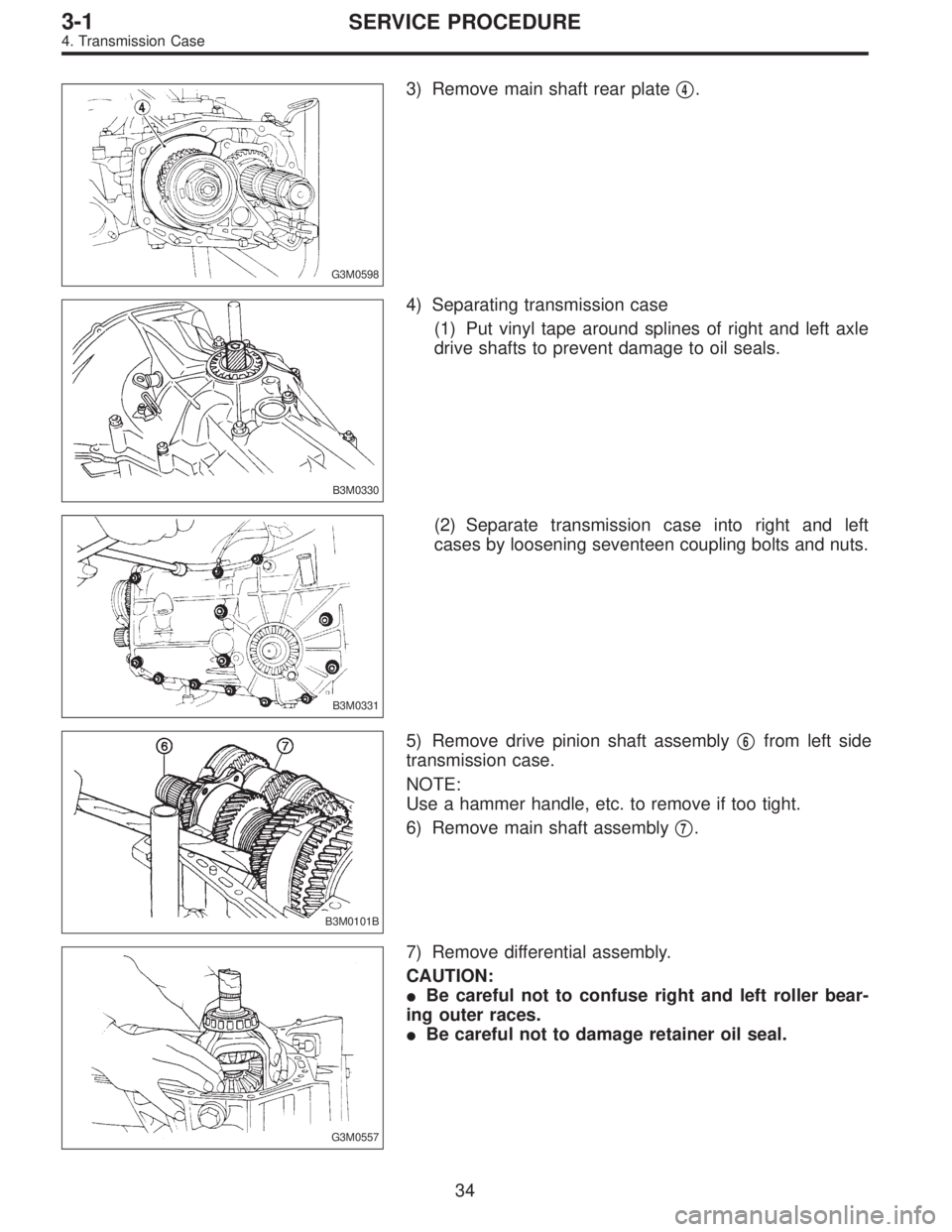
G3M0598
3) Remove main shaft rear plate�4.
B3M0330
4) Separating transmission case
(1) Put vinyl tape around splines of right and left axle
drive shafts to prevent damage to oil seals.
B3M0331
(2) Separate transmission case into right and left
cases by loosening seventeen coupling bolts and nuts.
B3M0101B
5) Remove drive pinion shaft assembly�6from left side
transmission case.
NOTE:
Use a hammer handle, etc. to remove if too tight.
6) Remove main shaft assembly�
7.
G3M0557
7) Remove differential assembly.
CAUTION:
�Be careful not to confuse right and left roller bear-
ing outer races.
�Be careful not to damage retainer oil seal.
34
3-1SERVICE PROCEDURE
4. Transmission Case
Page 826 of 2890

Abnormal noise will develop and finally it will become impossible to continue to run due to broken pieces obstructi")
Symptom and possible cause Remedy
4. Broken differential (case, gear, bearing, etc.)
Abnormal noise will develop and finally it will become impossible to continue to run due to broken pieces obstructing the gear
revolution.
(a) Insufficient or improper oil Disassemble differential and replace broken components and
at the same time check other components for any trouble,
and replace if necessary.
(b) Use of vehicle under severe conditions such as excessive
load and improper use of clutchReadjust bearing preload and backlash and face contact of
gears.
(c) Improper adjustment of taper roller bearing Adjust.
(d) Improper adjustment of drive pinion and hypoid driven
gearAdjust.
(e) Excessive backlash due to worn differential side gear,
washer or differential pinionAdd recommended oil to specified level. Do not use vehicle
under severe operating conditions.
(f) Loose hypoid driven gear clamping bolts Tighten.
5. Differential and hypoid gear noises
Troubles of the differential and hypoid gear always appear as noise problems. Therefore noise is the first indication of the
trouble. However noises from the engine, muffler, tire, exhaust gas, bearing, body, etc. are easily mistaken for the differential
noise. Pay special attention to the hypoid gear noise because it is easily confused with other gear noises. There are the
following four kinds of noises.
(1) Gear noise when driving: If noise increases as vehicle speed increases it may be due to insufficient gear oil, incorrect
gear engagement, damaged gears, etc.
(2) Gear noise when coasting: Damaged gears due to maladjusted bearings and incorrect shim adjustment
(3) Bearing noise when driving or when coasting: Cracked, broken or damaged bearings
(4) Noise which mainly occurs when turning: Unusual noise from differential side gear, differential pinion, differential pinion
shaft, etc.
(a) Insufficient oil Lubricate.
(b) Improper adjustment of hypoid driven gear and drive
pinionCheck tooth contact.
(c) Worn teeth of hypoid driven gear and drive pinion Replace as a set.
Readjust bearing preload.
(d) Loose roller bearing Readjust hypoid driven gear to drive pinion backlash and
check tooth contact.
(e) Distorted hypoid driven gear or differential case Replace.
(f) Worn washer and differential pinion shaft Replace.
70
3-1DIAGNOSTICS
1. Manual Transmission and Differential
Page 869 of 2890

G3M0870
D: TRANSFER CLUTCH PRESSURE TEST
Check transfer clutch pressure in accordance with the fol-
lowing chart in the same manner as with line pressure.
ST 499897700 OIL PRESSURE ADAPTER SET
ST 498575400 OIL PRESSURE GAUGE ASSY
AWD mode:“D”range
FWD mode:“P”range, engine speed 2000 rpm
CAUTION:
Before setting in FWD mode, install spare fuse on FWD
mode switch.
Unit: kPa (kg/cm2, psi)
Duty ratio
(%)AWD mode FWD mode
5667—804
(6.8—8.2, 97—117)667—804
(6.8—8.2, 97—117)
40137—226
(1.4—2.3, 20—33)—
950
(0, 0)—
If oil pressure is not produced or if it does not change in the
AWD mode, the duty solenoid C or transfer valve assem-
bly may be malfunctioning. If oil pressure is produced in the
FWD mode, the problem is similar to that in the AWD
mode.
E: ROAD TEST
1. GENERAL
Road tests should be conducted to properly diagnose the
condition of the automatic transmission.
CAUTION:
When performing test, do not exceed posted speed
limit.
2. CHECKING FOR SHIFT PATTERNS
Check“kick-down”.
D range: 1st
←
→2nd←
→3rd←
→4th
3 range: 1st←
→2nd←
→3rd←4th
2 range: 2nd←3rd←4th
1 range: 1st←2nd←3rd←4th
3. CHECK FOR ENGINE BRAKE OPERATION
Engine brake operation:
D range→4th gear
3 range→3rd gear
2 range→2nd gear
1 range→1st gear
43
3-2SERVICE PROCEDURE
3. Performance Test
Page 886 of 2890
 Install the circlip to the axle shaft, insert the shaft into
the differential assembly, and tap it into position with a
plastic hammer.
Thrust play:
Approx. 0.3—0.5 mm (0.012—0.020 in)
CAUTION:")
7) Install the circlip to the axle shaft, insert the shaft into
the differential assembly, and tap it into position with a
plastic hammer.
Thrust play:
Approx. 0.3—0.5 mm (0.012—0.020 in)
CAUTION:
�If no play is felt, check whether the shaft is fully
inserted. If shaft insertion is correct, replace the axle
shaft.
�Be sure to use a new circlip.
G3M0368
8) Wrap vinyl tape around the splined portion of the axle
shaft.
9) Install the oil seal and outer race (taper roller bearing)
to the differential side retainer. Then screw in the retainer
and the O-ring after coating the threads with oil.
CAUTION:
�Pay attention not to damage the oil seal lips.
�Do not confuse the RH and LH oil seals.
�Keep the O-ring removed from the retainer.
B3M0352A
10) Using the ST, screw in the retainer until light contact
is felt.
ST 499787000 WRENCH ASSY
NOTE:
Screw in the RH side slightly deeper than the LH side.
G3M0382
11) Hypoid gear backlash adjustment and tooth contact
check
(1) Assemble the drive pinion assembly to the oil pump
housing.
CAUTION:
�Be careful not to bend the shims.
[W8C0].>
�Be careful not to force the pinion against the hous-
ing bore.
60
3-2SERVICE PROCEDURE
4. Overall Transmission
 Disconnect battery ground cable.
B5M0024A
2) Remove lower cover and then disconnect connectors.
3) Lower transmission control module.
4) Remove th")
 Disconnect battery ground cable.
B5M0024A
2) Remove lower cover and then disconnect connectors.
3) Lower transmission control module.
4) Remo")