Page 1986 of 2890
OBD0304
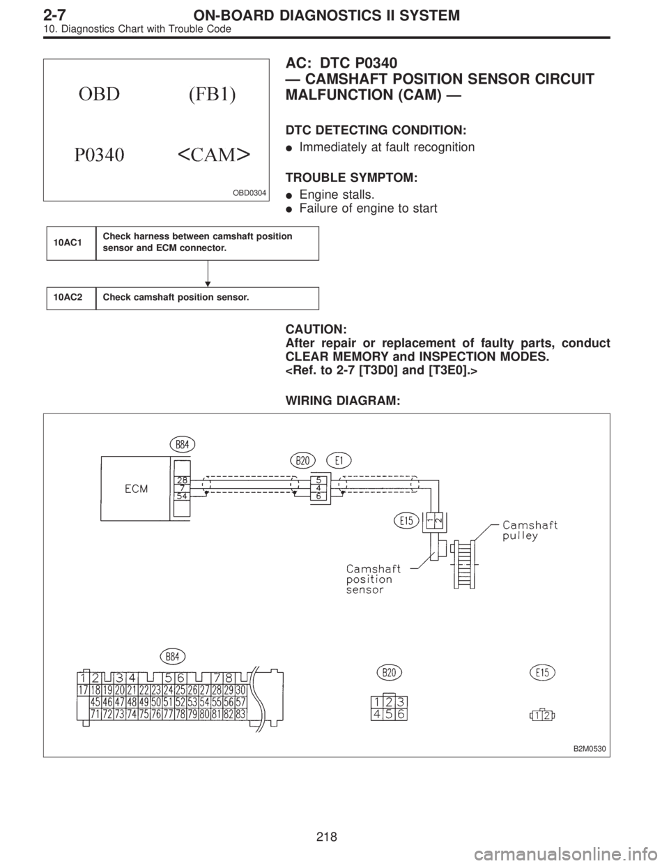
AC: DTC P0340
—CAMSHAFT POSITION SENSOR CIRCUIT
MALFUNCTION (CAM)—
DTC DETECTING CONDITION:
�Immediately at fault recognition
TROUBLE SYMPTOM:
�Engine stalls.
�Failure of engine to start
10AC1Check harness between camshaft position
sensor and ECM connector.
10AC2Check camshaft position sensor.
CAUTION:
After repair or replacement of faulty parts, conduct
CLEAR MEMORY and INSPECTION MODES.
WIRING DIAGRAM:
B2M0530
�
218
2-7ON-BOARD DIAGNOSTICS II SYSTEM
10. Diagnostics Chart with Trouble Code
Page 2034 of 2890
OBD0340
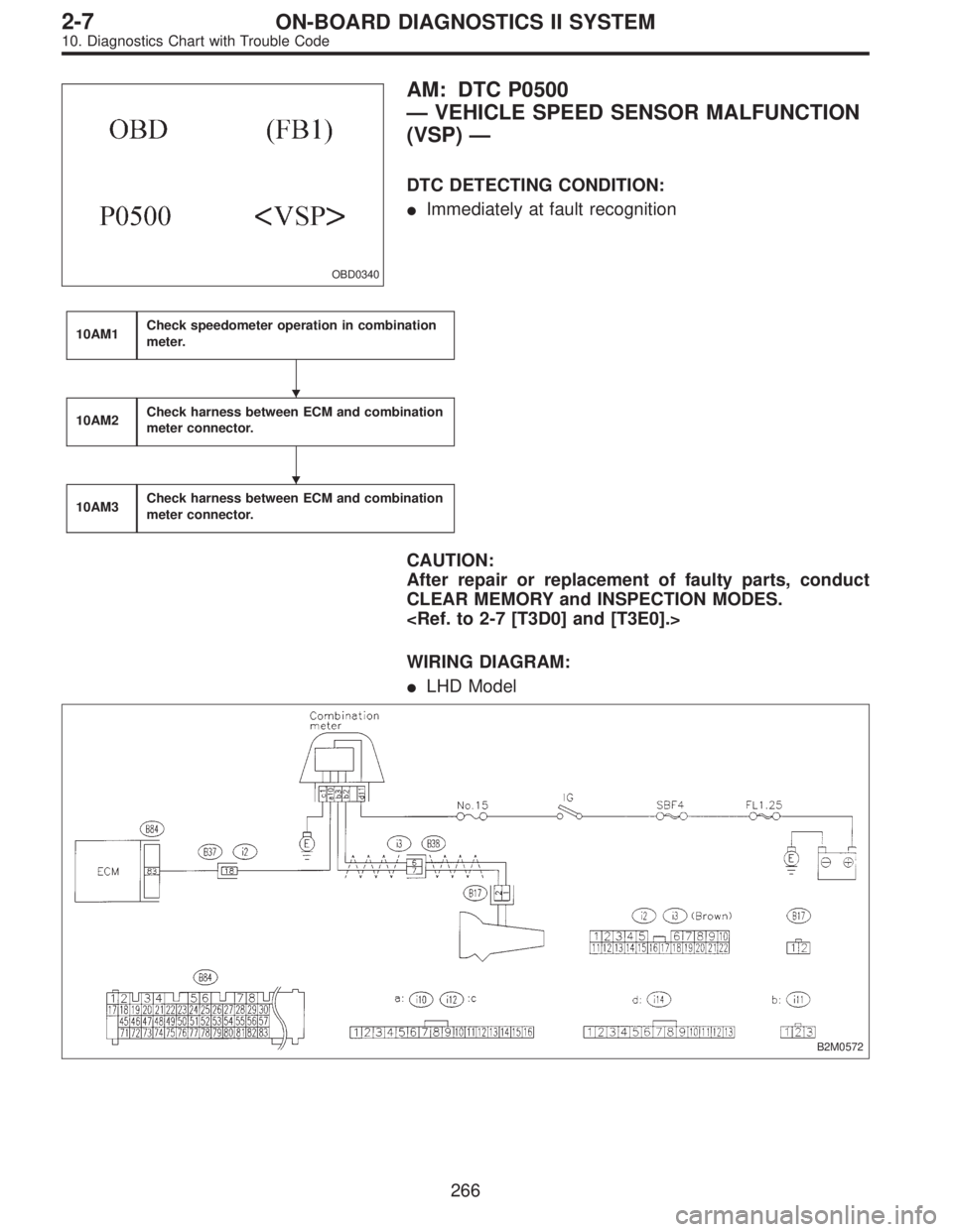
AM: DTC P0500
—VEHICLE SPEED SENSOR MALFUNCTION
(VSP)—
DTC DETECTING CONDITION:
�Immediately at fault recognition
10AM1Check speedometer operation in combination
meter.
10AM2Check harness between ECM and combination
meter connector.
10AM3Check harness between ECM and combination
meter connector.
CAUTION:
After repair or replacement of faulty parts, conduct
CLEAR MEMORY and INSPECTION MODES.
WIRING DIAGRAM:
�LHD Model
B2M0572
�
�
266
2-7ON-BOARD DIAGNOSTICS II SYSTEM
10. Diagnostics Chart with Trouble Code
Page 2035 of 2890
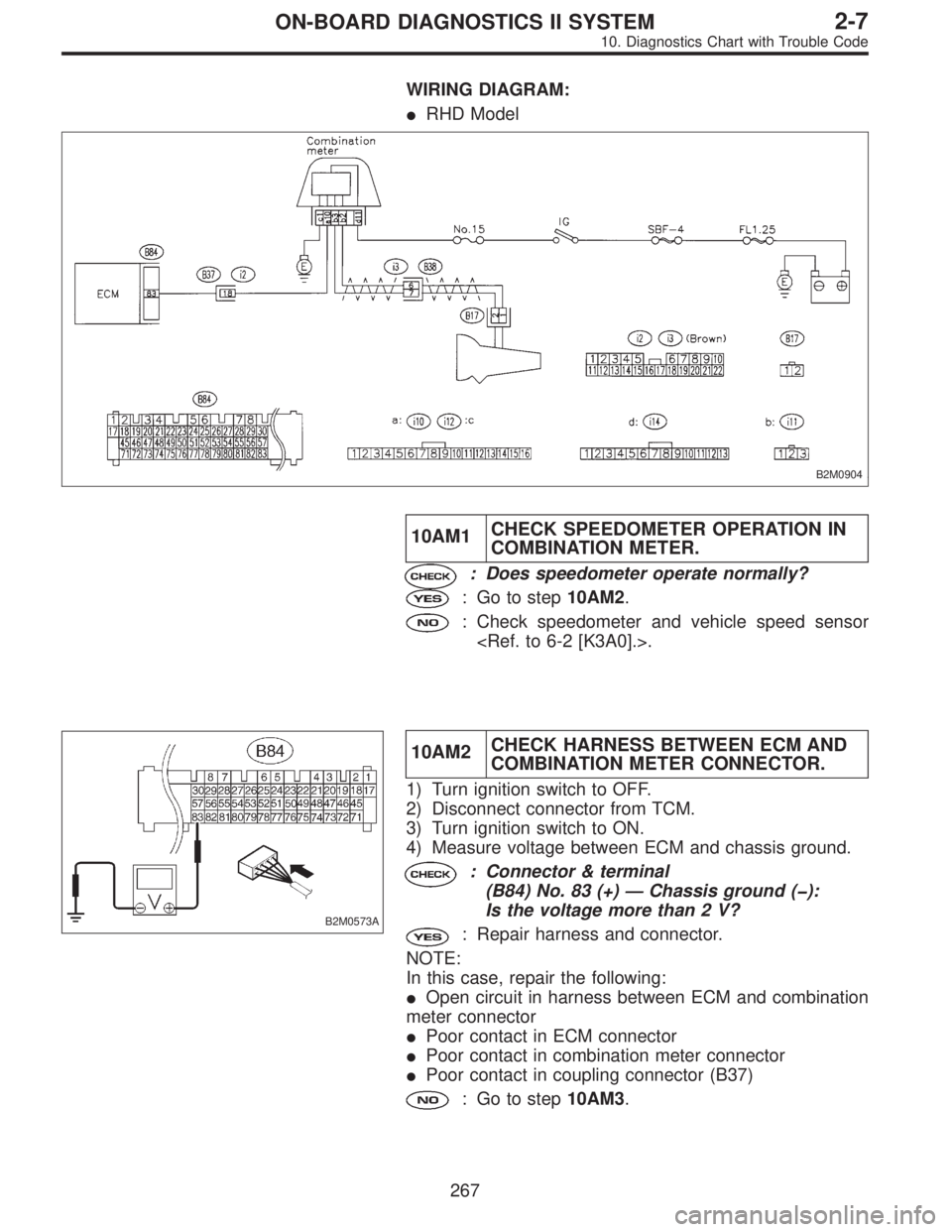
WIRING DIAGRAM:
�RHD Model
B2M0904
10AM1CHECK SPEEDOMETER OPERATION IN
COMBINATION METER.
: Does speedometer operate normally?
: Go to step10AM2.
: Check speedometer and vehicle speed sensor
.
B2M0573A
10AM2CHECK HARNESS BETWEEN ECM AND
COMBINATION METER CONNECTOR.
1) Turn ignition switch to OFF.
2) Disconnect connector from TCM.
3) Turn ignition switch to ON.
4) Measure voltage between ECM and chassis ground.
: Connector & terminal
(B84) No. 83 (+)—Chassis ground (�):
Is the voltage more than 2 V?
: Repair harness and connector.
NOTE:
In this case, repair the following:
�Open circuit in harness between ECM and combination
meter connector
�Poor contact in ECM connector
�Poor contact in combination meter connector
�Poor contact in coupling connector (B37)
: Go to step10AM3.
267
2-7ON-BOARD DIAGNOSTICS II SYSTEM
10. Diagnostics Chart with Trouble Code
Page 2046 of 2890
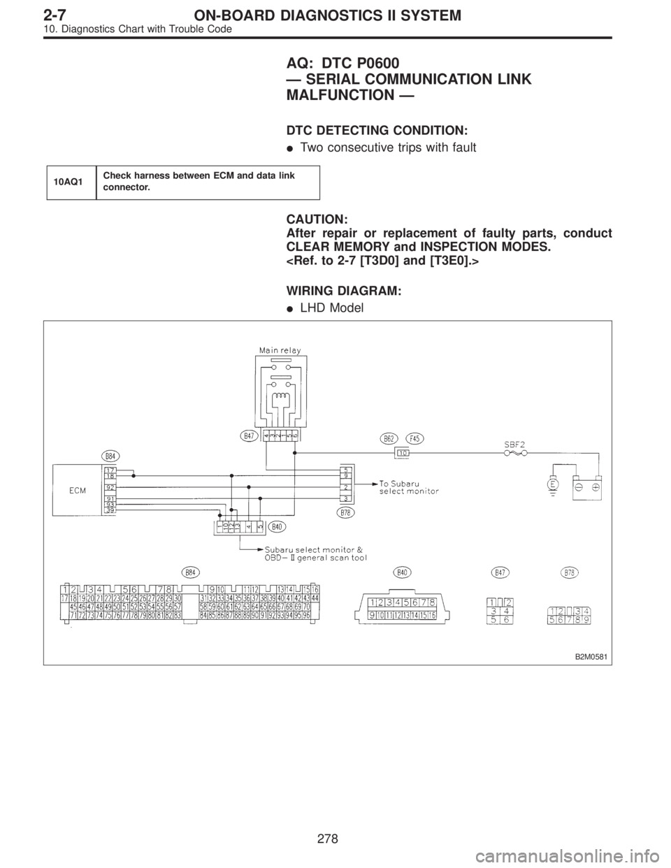
AQ: DTC P0600
—SERIAL COMMUNICATION LINK
MALFUNCTION—
DTC DETECTING CONDITION:
�Two consecutive trips with fault
10AQ1Check harness between ECM and data link
connector.
CAUTION:
After repair or replacement of faulty parts, conduct
CLEAR MEMORY and INSPECTION MODES.
WIRING DIAGRAM:
�LHD Model
B2M0581
278
2-7ON-BOARD DIAGNOSTICS II SYSTEM
10. Diagnostics Chart with Trouble Code
Page 2051 of 2890
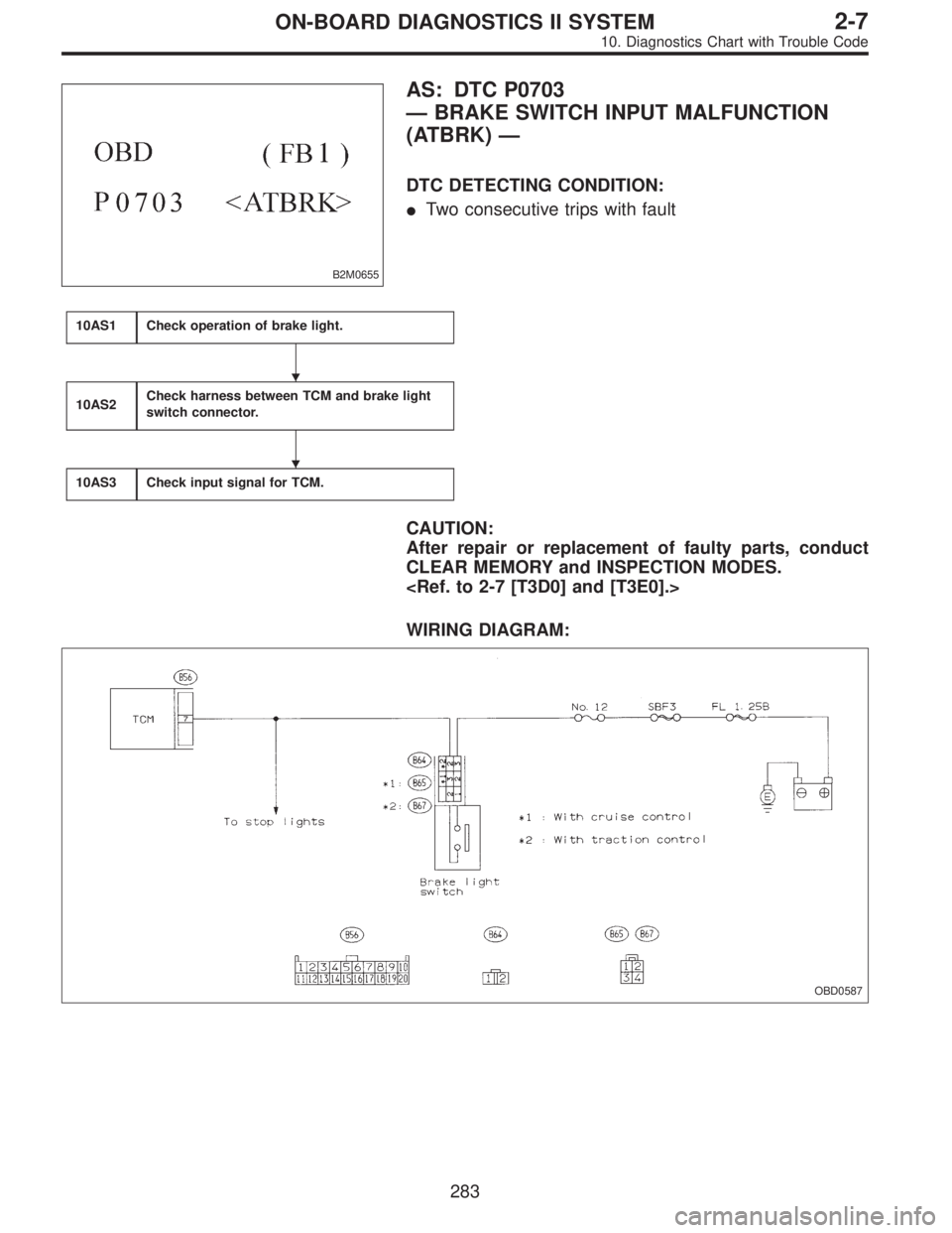
B2M0655
AS: DTC P0703
—BRAKE SWITCH INPUT MALFUNCTION
(ATBRK)—
DTC DETECTING CONDITION:
�Two consecutive trips with fault
10AS1Check operation of brake light.
10AS2Check harness between TCM and brake light
switch connector.
10AS3Check input signal for TCM.
CAUTION:
After repair or replacement of faulty parts, conduct
CLEAR MEMORY and INSPECTION MODES.
WIRING DIAGRAM:
OBD0587
�
�
283
2-7ON-BOARD DIAGNOSTICS II SYSTEM
10. Diagnostics Chart with Trouble Code
Page 2083 of 2890
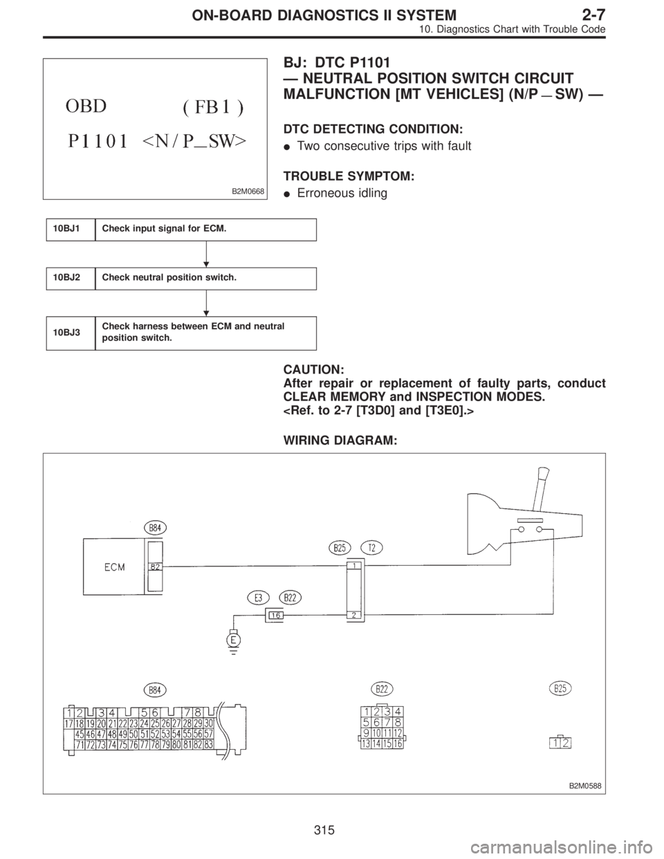
B2M0668
BJ: DTC P1101
—NEUTRAL POSITION SWITCH CIRCUIT
MALFUNCTION [MT VEHICLES] (N/P
—SW)—
DTC DETECTING CONDITION:
�Two consecutive trips with fault
TROUBLE SYMPTOM:
�Erroneous idling
10BJ1Check input signal for ECM.
10BJ2Check neutral position switch.
10BJ3Check harness between ECM and neutral
position switch.
CAUTION:
After repair or replacement of faulty parts, conduct
CLEAR MEMORY and INSPECTION MODES.
WIRING DIAGRAM:
B2M0588
�
�
315
2-7ON-BOARD DIAGNOSTICS II SYSTEM
10. Diagnostics Chart with Trouble Code
Page 2096 of 2890
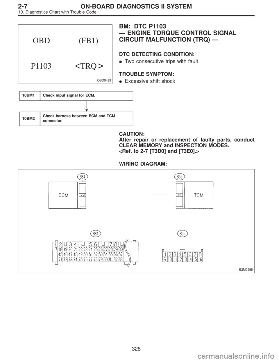
OBD0489
BM: DTC P1103
—ENGINE TORQUE CONTROL SIGNAL
CIRCUIT MALFUNCTION (TRQ)—
DTC DETECTING CONDITION:
�Two consecutive trips with fault
TROUBLE SYMPTOM:
�Excessive shift shock
10BM1Check input signal for ECM.
10BM2Check harness between ECM and TCM
connector.
CAUTION:
After repair or replacement of faulty parts, conduct
CLEAR MEMORY and INSPECTION MODES.
WIRING DIAGRAM:
B2M0598
�
328
2-7ON-BOARD DIAGNOSTICS II SYSTEM
10. Diagnostics Chart with Trouble Code
Page 2130 of 2890
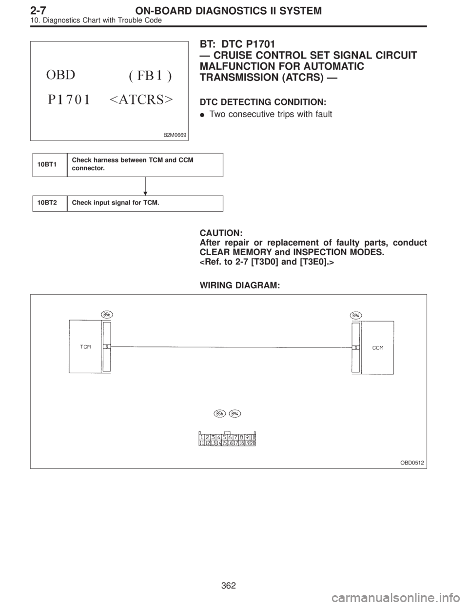
B2M0669
BT: DTC P1701
—CRUISE CONTROL SET SIGNAL CIRCUIT
MALFUNCTION FOR AUTOMATIC
TRANSMISSION (ATCRS)—
DTC DETECTING CONDITION:
�Two consecutive trips with fault
10BT1Check harness between TCM and CCM
connector.
10BT2Check input signal for TCM.
CAUTION:
After repair or replacement of faulty parts, conduct
CLEAR MEMORY and INSPECTION MODES.
WIRING DIAGRAM:
OBD0512
�
362
2-7ON-BOARD DIAGNOSTICS II SYSTEM
10. Diagnostics Chart with Trouble Code