Page 2133 of 2890
OBD0516
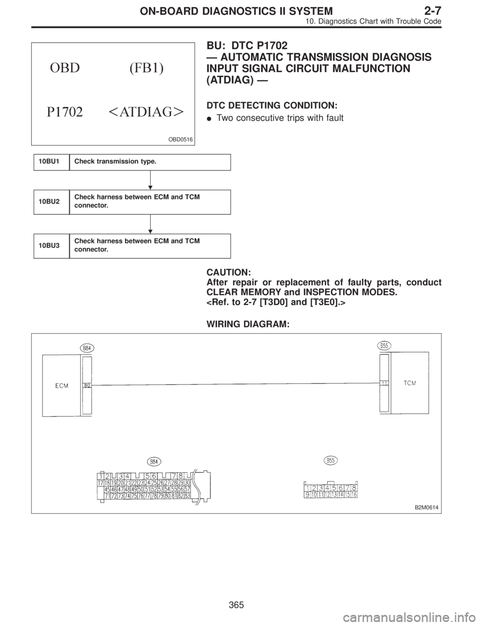
BU: DTC P1702
—AUTOMATIC TRANSMISSION DIAGNOSIS
INPUT SIGNAL CIRCUIT MALFUNCTION
(ATDIAG)—
DTC DETECTING CONDITION:
�Two consecutive trips with fault
10BU1Check transmission type.
10BU2Check harness between ECM and TCM
connector.
10BU3Check harness between ECM and TCM
connector.
CAUTION:
After repair or replacement of faulty parts, conduct
CLEAR MEMORY and INSPECTION MODES.
WIRING DIAGRAM:
B2M0614
�
�
365
2-7ON-BOARD DIAGNOSTICS II SYSTEM
10. Diagnostics Chart with Trouble Code
Page 2138 of 2890
BW:—AT/MT IDENTIFICATION CIRCUIT
MALFUNCTION [MT VEHICLES]—
10BW1Check harness between ECM connector and
engine grounding terminal.
CAUTION:
After repair or replacement of faulty parts, conduct
CLEAR MEMORY and INSPECTION MODES.
WIRING DIAGRAM:
B2M0617
370
2-7ON-BOARD DIAGNOSTICS II SYSTEM
10. Diagnostics Chart with Trouble Code
Page 2365 of 2890
WIRING DIAGRAM:
B4M1034
B4M0800A
7C1
CHECK DIAGNOSIS TERMINAL.
Measure resistance between diagnosis terminals (B81)
and chassis ground.
: Terminals
Diagnosis terminal (A)—Chassis ground:
Diagnosis terminal (B)—Chassis ground:
Is the resistance less than 0.5Ω?
: Go to step7C2.
: Repair diagnosis terminal harness.
25
4-4cBRAKES [ABS 5.3 TYPE]
7. Diagnostics Chart for ABS Warning Light Circuit and Diagnosis Circuit Failure
Page 2537 of 2890
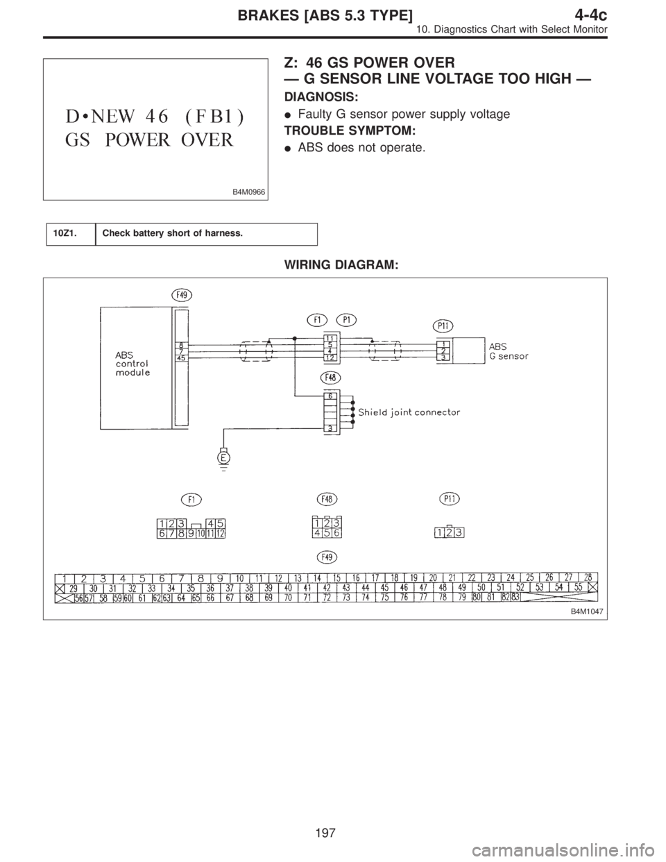
B4M0966
Z: 46 GS POWER OVER
—G SENSOR LINE VOLTAGE TOO HIGH—
DIAGNOSIS:
�Faulty G sensor power supply voltage
TROUBLE SYMPTOM:
�ABS does not operate.
10Z1.Check battery short of harness.
WIRING DIAGRAM:
B4M1047
197
4-4cBRAKES [ABS 5.3 TYPE]
10. Diagnostics Chart with Select Monitor
Page 2600 of 2890
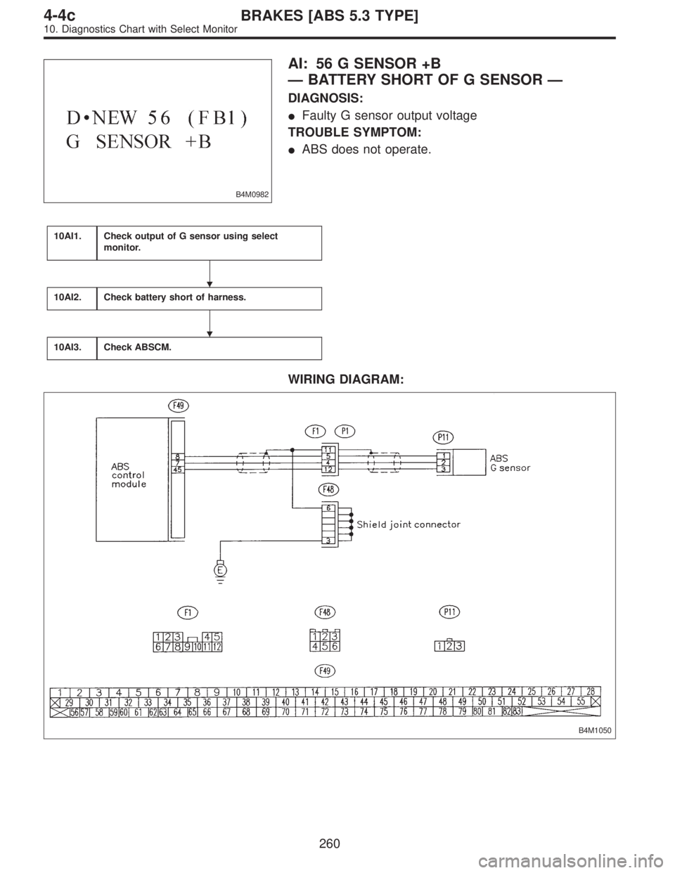
B4M0982
AI: 56 G SENSOR +B
—BATTERY SHORT OF G SENSOR—
DIAGNOSIS:
�Faulty G sensor output voltage
TROUBLE SYMPTOM:
�ABS does not operate.
10AI1.Check output of G sensor using select
monitor.
10AI2.Check battery short of harness.
10AI3.Check ABSCM.
WIRING DIAGRAM:
B4M1050
�
�
260
4-4cBRAKES [ABS 5.3 TYPE]
10. Diagnostics Chart with Select Monitor
Page 2732 of 2890
1. General Description
1. HOW TO USE THIS MANUAL
The description of the electrical system is divided into the
charging system, starting system, etc.
1) First, open to the necessary electrical system section
and wiring diagram.
2) Next, open the foldout page of the electrical wiring dia-
gram. By observing the electrical wiring harness’ illustra-
tions (front, instrument panel, etc.), the wiring diagram con-
nector can be located.
G6M0192
G6M0193
2. WIRING DIAGRAM
The wiring diagram of each system is illustrated so that you
can understand the path through which the electric current
flows from the battery.
Sketches and codes are used in the diagrams. They should
read as follows:
1) Each connector and its terminal position are indicated
by a sketch of the connector in a disconnected state which
is viewed from the front, as shown in figure.
2
6-3WIRING DIAGRAM
1. General Description
Page 2733 of 2890
 The number of poles or pins, presence of a lock, and pin
number of each terminal are indicated in the sketch of each
connector.
In the sketch, the highest pole number refers to the num-
ber of pole")
2) The number of poles or pins, presence of a lock, and pin
number of each terminal are indicated in the sketch of each
connector.
In the sketch, the highest pole number refers to the num-
ber of poles which the connector has. For example, the
sketch of the connector shown in figure indicates the con-
nector has 9 poles.
Connector used in vehicleConnector shown in wiring diagram
Sketch Symbol Number of poles
G6M0194G6M0196
G6M0198
Numbered in order from
upper right to lower left.
G6M0195G6M0197
Numbered in order from
upper left to lower right.
G6M0199
When one set of connectors is viewed from the front side,
the pole numbers of one connector are symmetrical to
those of the other. When these two connectors are con-
nected as a unit, the poles which have the same number
are joined.
3) Electrical wiring harness
The connectors are numbered along with the number of
poles, external colors, and mating connections in the
accompanying list.
3
6-3WIRING DIAGRAM
1. General Description
Page 2735 of 2890
 The table below lists the nominal sectional areas and
allowable currents of the wires.
Nominal
sectional area
mm
2
No. of strands/
strand diameterOutside
diameter of
finished wiring
mmAllowable
cur")
8) The table below lists the nominal sectional areas and
allowable currents of the wires.
Nominal
sectional area
mm
2
No. of strands/
strand diameterOutside
diameter of
finished wiring
mmAllowable
current
Amps/40°C
0.3 7/0.26 1.8 7
0.5 7/0.32 2.2 (or 2.0) 12
0.75 30/0.18 2.6 (or 2.4) 16
0.85 11/0.32 2.4 (or 2.2) 16
1.25 16/0.32 2.7 (or 2.5) 21
2 26/0.32 3.1 (or 2.9) 28
3 41/0.32 3.8 (or 3.6) 38
5 65/0.32 4.6 (or 4.4) 51
8 50/0.45 5.5 67
CAUTION:
When replacing or repairing a wire, be sure to use the
same size and type of the wire which was originally
used.
NOTE:
�The allowable current in the above table indicates the
tolerable amperage of each wire at an ambient tempera-
ture of 40°C (104°F).
�The allowable current changes with ambient tempera-
ture. Also, it changes if a bundle of more than two wires is
used.
G6M0203
9) Each unit is directly grounded to the body or indirectly
grounds through a harness ground terminal. Different sym-
bols are used in the wiring diagram to identify the two
grounding systems.
The ground points shown in the wiring diagram refer to the
following:
�GBBody ground
�GEEngine ground
�GRRadio ground
�GDRear defogger ground
All wiring harnesses are provided with a ground point which
should be securely connected.
5
6-3WIRING DIAGRAM
1. General Description
![SUBARU LEGACY 1996 Service Repair Manual BW:—AT/MT IDENTIFICATION CIRCUIT
MALFUNCTION [MT VEHICLES]—
10BW1Check harness between ECM connector and
engine grounding terminal.
CAUTION:
After repair or replacement of faulty parts, conduct
CL](/manual-img/17/57433/w960_57433-2137.png "SUBARU LEGACY 1996 Service Repair Manual BW:—AT/MT IDENTIFICATION CIRCUIT
MALFUNCTION [MT VEHICLES]—
10BW1Check harness between ECM connector and
engine grounding terminal.
CAUTION:
After repair or replacement of faulty parts, conduct
CL")

and chassis ground.
: Terminals
Diagnosis terminal (A)—Chassis ground:
Diagnosis t")
 First, open to the necessary electrical system s")