Page 1586 of 2890
B5M0102
10) Remove front sensor.
B: INSTALLATION
Installation is in reverse order of removal procedures.
5. Main Harness
A: REMOVAL
1) Turn ignition switch off.
2) Disconnect ground cable from battery and wait for at
least 20 seconds before starting work.
G5M0312
3) Remove lower cover.
Disconnect airbag connector (AB3) and (AB8) below steer-
ing column.
CAUTION:
Do not reconnect airbag connector at steering column
until main harness are securely re-installed.
G5M0313
4) Remove console box. Discon-
nect 12-pin yellow connector (AB6) from airbag control
module.
15
5-5SERVICE PROCEDURE
4. Front Sensor - 5. Main Harness
Page 1596 of 2890
G5M0291
1. Precaution
1) If any of the airbag system parts such as sensors, air-
bag module, airbag control module and harness are dam-
aged or deformed, replace with new genuine parts.
G5M0292
2) When servicing, be sure to turn the ignition switch off,
disconnect the negative (�) battery terminal then the posi-
tive (+) terminal in advance, and wait for more than 20
seconds before starting work.
G5M0293
3) When checking the system, be sure to use a digital cir-
cuit tester. Use of an analog circuit tester may cause the
airbag to activate erroneously. Do not directly apply the
tester probe to any connector terminal of the airbag. When
checking, use a test harness.
G5M0294
4
5-5bSERVICE PROCEDURE
1. Precaution
Page 1600 of 2890

G5M0311
3. FRONT SENSOR
Inspection standard:
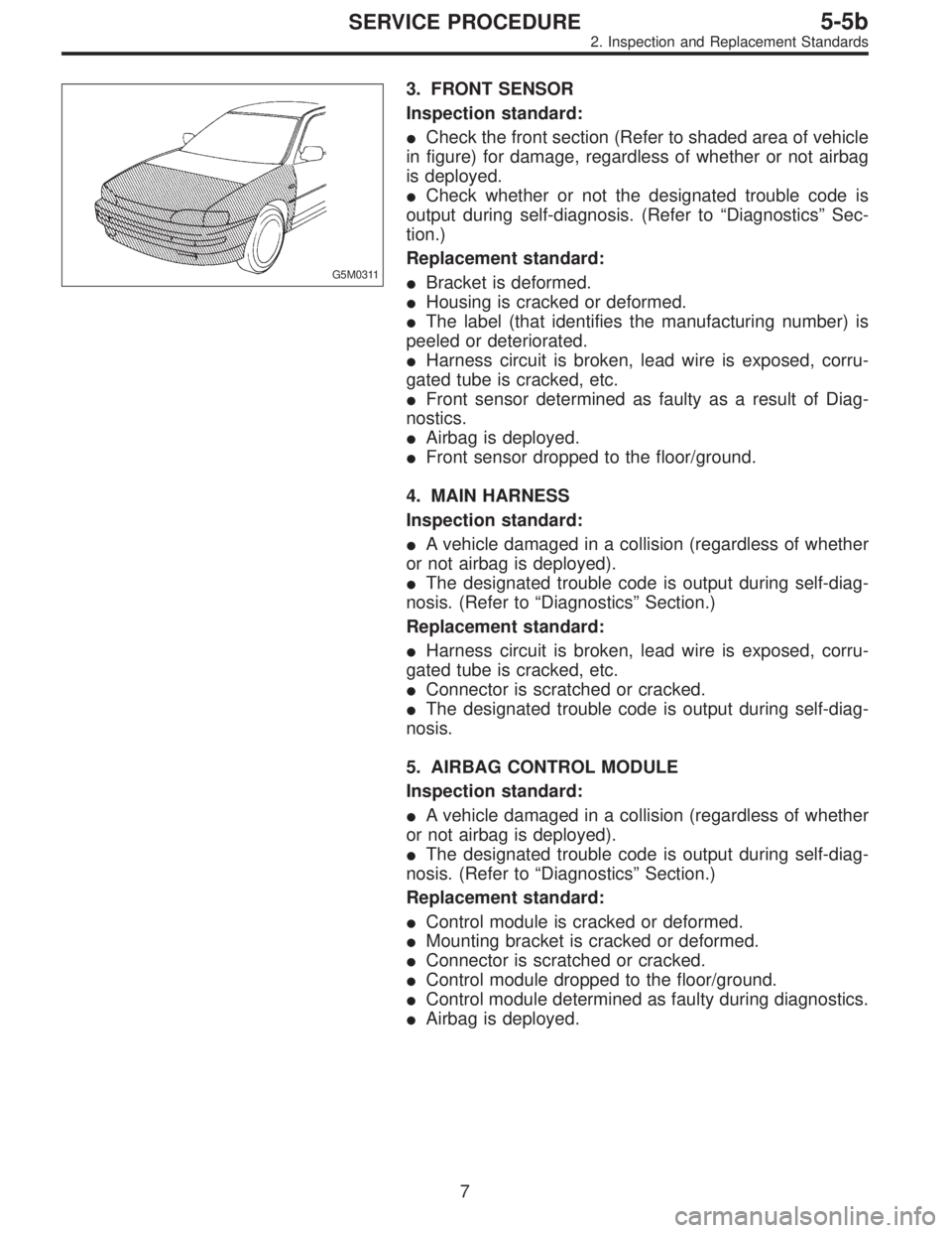
�Check the front section (Refer to shaded area of vehicle
in figure) for damage, regardless of whether or not airbag
is deployed.
�Check whether or not the designated trouble code is
output during self-diagnosis. (Refer to“Diagnostics”Sec-
tion.)
Replacement standard:
�Bracket is deformed.
�Housing is cracked or deformed.
�The label (that identifies the manufacturing number) is
peeled or deteriorated.
�Harness circuit is broken, lead wire is exposed, corru-
gated tube is cracked, etc.
�Front sensor determined as faulty as a result of Diag-
nostics.
�Airbag is deployed.
�Front sensor dropped to the floor/ground.
4. MAIN HARNESS
Inspection standard:
�A vehicle damaged in a collision (regardless of whether
or not airbag is deployed).
�The designated trouble code is output during self-diag-
nosis. (Refer to“Diagnostics”Section.)
Replacement standard:
�Harness circuit is broken, lead wire is exposed, corru-
gated tube is cracked, etc.
�Connector is scratched or cracked.
�The designated trouble code is output during self-diag-
nosis.
5. AIRBAG CONTROL MODULE
Inspection standard:
�A vehicle damaged in a collision (regardless of whether
or not airbag is deployed).
�The designated trouble code is output during self-diag-
nosis. (Refer to“Diagnostics”Section.)
Replacement standard:
�Control module is cracked or deformed.
�Mounting bracket is cracked or deformed.
�Connector is scratched or cracked.
�Control module dropped to the floor/ground.
�Control module determined as faulty during diagnostics.
�Airbag is deployed.
7
5-5bSERVICE PROCEDURE
2. Inspection and Replacement Standards
Page 1640 of 2890
B6M0557A
2) Disconnect mass air flow sensor connector.
3) Remove four clips securing air cleaner upper cover.
B6M0558
4) Loosen the clamp screw and separate air cleaner upper
cover from air intake duct.
5) Remove air cleaner element.
B6M0559A
6) Remove #3 spark plug cord by pulling boot, not cord
itself.
B6M0560
7) Remove spark plug with the spark plug socket.
8) Installation is in the reverse order of removal.
Tightening torque (Spark plug):
20.6±2.9 N⋅m (2.10±0.30 kg-m, 15.19±2.14 ft-lb)
26
6-1SERVICE PROCEDURE
3. Spark Plug
Page 1643 of 2890
B6M0557A
2) Disconnect mass air flow sensor connector.
3) Remove four clips securing air cleaner upper cover.
B6M0558
4) Loosen the clamp screw and separate air cleaner upper
cover from air intake duct.
B6M0565A
5) Remove air cleaner element and air cleaner case.
B6M0566A
6) Remove #1 spark plug cord by pulling boot, not cord
itself.
B6M0567A
7) After connecting�1spark plug socket,�2extension and
�
3Universal Joint to each other, securely set them over the
spark plug in cylinder head.
8) Cover ABS pipes with rag to prevent damage.
�
1Spark plug socket 16 mm (5/8 in)
�
2Extension
�
3Universal Joint
�
4Extension
�
5Ratchet
29
6-1SERVICE PROCEDURE
3. Spark Plug
Page 1645 of 2890
B6M0555A
3) Remove #2 spark plug cord by pulling boot, not cord
itself.
4) For subsequent procedures, refer to the procedure for
#1 spark plug.
CAUTION:
When removing spark plug, cover the ATF cooling
pipes with a rag to prevent damage.
G6M0095
3. #3 SPARK PLUG
1) Disconnect battery ground cable.
B6M0557A
2) Disconnect mass air flow sensor connector.
3) Remove four clips securing air cleaner upper cover.
B6M0558
4) Loosen the clamp screw and separate air cleaner upper
cover from air intake duct.
B6M0565A
5) Remove air cleaner element and air cleaner case.
31
6-1SERVICE PROCEDURE
3. Spark Plug
Page 1696 of 2890

14. Vehicle Speed Sensor 2
A: GENERAL PRECAUTIONS
1) Be careful not to drop or bump sensor as this may break
built-in magnet.
2) Drive key is designed to separate from vehicle speed
sensor 2. Be careful not to lose it or forget to install.
3) Vehicle speed sensor 2 is installed in part (which con-
tains bearings, etc., finished to a high degree of accuracy).
Do not allow foreign matter (filings, sand, etc.) to get into
it.
4) When checking output of vehicle speed sensor 2 as a
single unit, ensure test leads are connected to their correct
terminals. Failure to do this may damage internal IC.
5) Discard vehicle speed sensor 2 after removal; replace
with new one.
B: REMOVAL
CAUTION:
�Be careful when removing vehicle speed sensor 2
immediately after driving vehicle for a while, as tem-
perature around it is high.
�Before removing vehicle speed sensor 2, clean dirt,
etc. from surrounding areas. Take care not to allow
foreign matter to get into mounting hole.
B2M0211
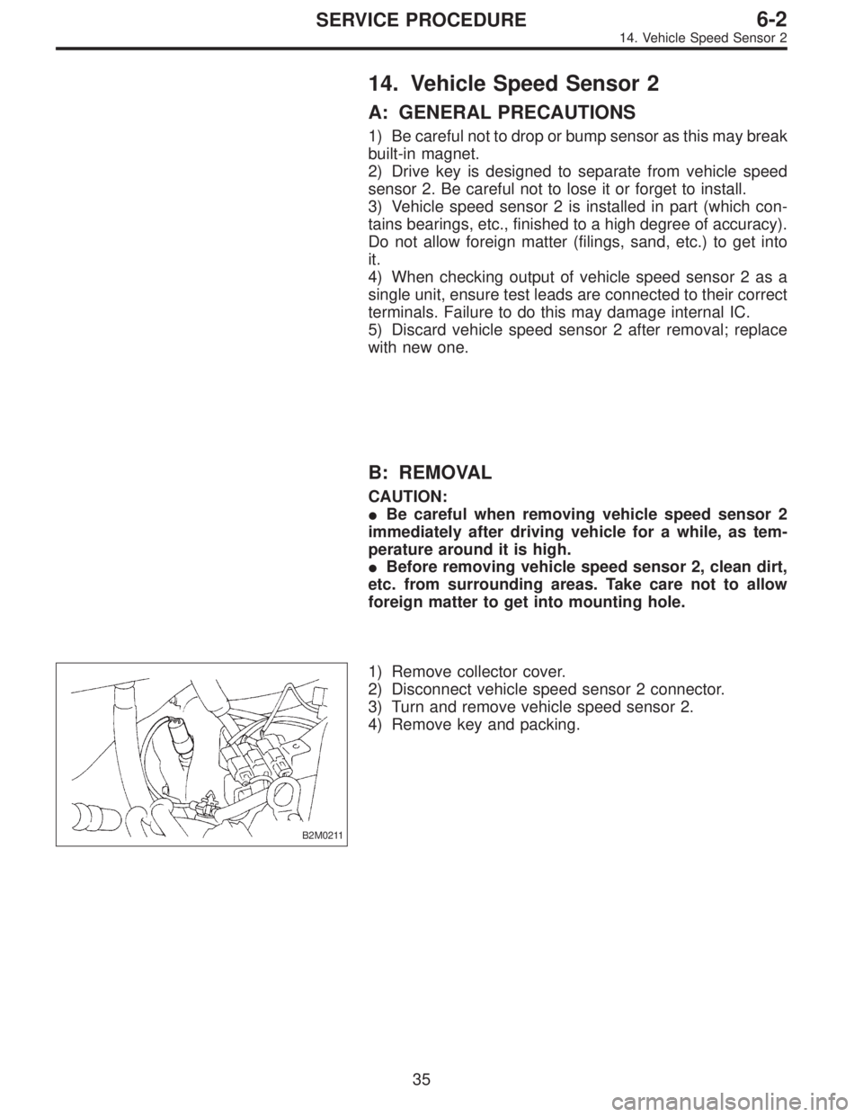
1) Remove collector cover.
2) Disconnect vehicle speed sensor 2 connector.
3) Turn and remove vehicle speed sensor 2.
4) Remove key and packing.
35
6-2SERVICE PROCEDURE
14. Vehicle Speed Sensor 2
Page 1697 of 2890
C: INSTALLATION
CAUTION:
�Ensure sensor mounting hole is clean and free of
foreign matter.
�Apply grease to tip end of key to prevent key from
falling off sensor.
�Align tip end of key with key groove on end of
speedometer shaft during installation.
1) Hand tighten vehicle speed sensor 2, then tighten it
using suitable tool.
Tightening torque required for sensor to reach bottom of
transmission is as follows:
Tightening torque:
0.39—0.88 N⋅m (4.0—9.0 kg-cm, 3.5—7.8 in-lb)
CAUTION:
�When torque must be applied that exceeds 0.88 N⋅m
(9.0 kg-cm, 7.8 in-lb), the key and key groove on end of
speedometer may not be aligned properly. Remove the
key, align it correctly and reassemble.
�Sensor threads are secured by Locktite. The reas-
sembly must be completed within 5 minutes before
Locktite dries.
2) Tighten vehicle speed sensor 2 further to specified
torque.
Tightening torque:
5.9±1.5 N⋅m (60±15 kg-cm, 52±13 in-lb)
36
6-2SERVICE PROCEDURE
14. Vehicle Speed Sensor 2