Page 1780 of 2890
B: AUTOMATIC TRANSMISSION
1. ELECTRONIC-HYDRAULIC CONTROL SYSTEM
The electronic-hydraulic control system consists of various
sensors and switches, a transmission control module
(TCM) and the hydraulic controller including solenoid
valves. The system controls the transmission proper
including shift control, lock-up control, overrunning clutch
control, line pressure control and shift timing control. It also
controls the AWD transfer clutch. In other words, the sys-
tem detects various operating conditions from various input
signals and sends output signals to shift solenoids 1, 2 and
3 and duty solenoids A, B and C (a total of six solenoids).
12
2-7ON-BOARD DIAGNOSTICS II SYSTEM
1. General
Page 1783 of 2890
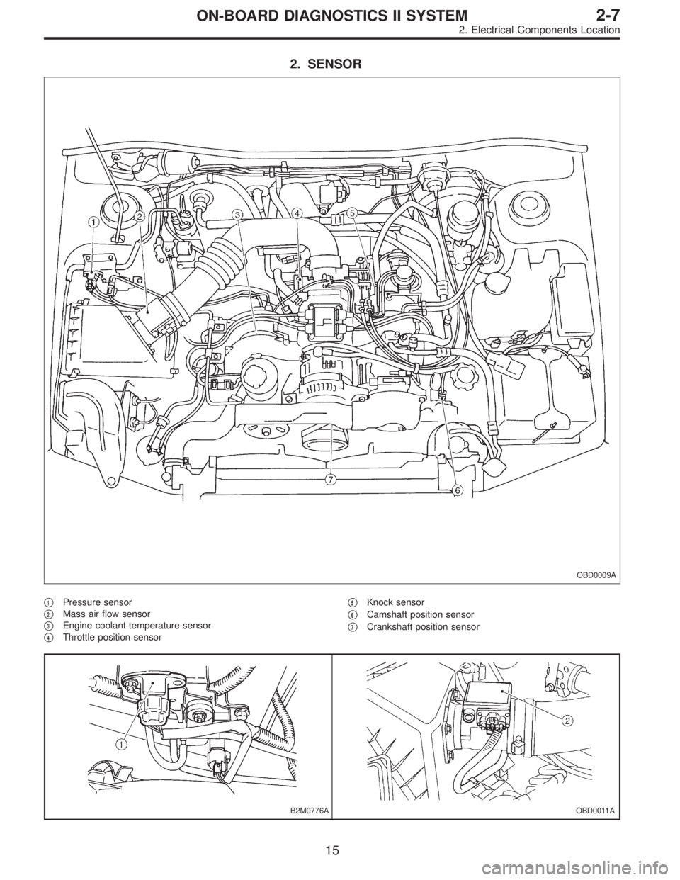
2. SENSOR
OBD0009A
�1Pressure sensor
�
2Mass air flow sensor
�
3Engine coolant temperature sensor
�
4Throttle position sensor�
5Knock sensor
�
6Camshaft position sensor
�
7Crankshaft position sensor
B2M0776AOBD0011A
15
2-7ON-BOARD DIAGNOSTICS II SYSTEM
2. Electrical Components Location
Page 1785 of 2890
B2M0471A
B2M0472A
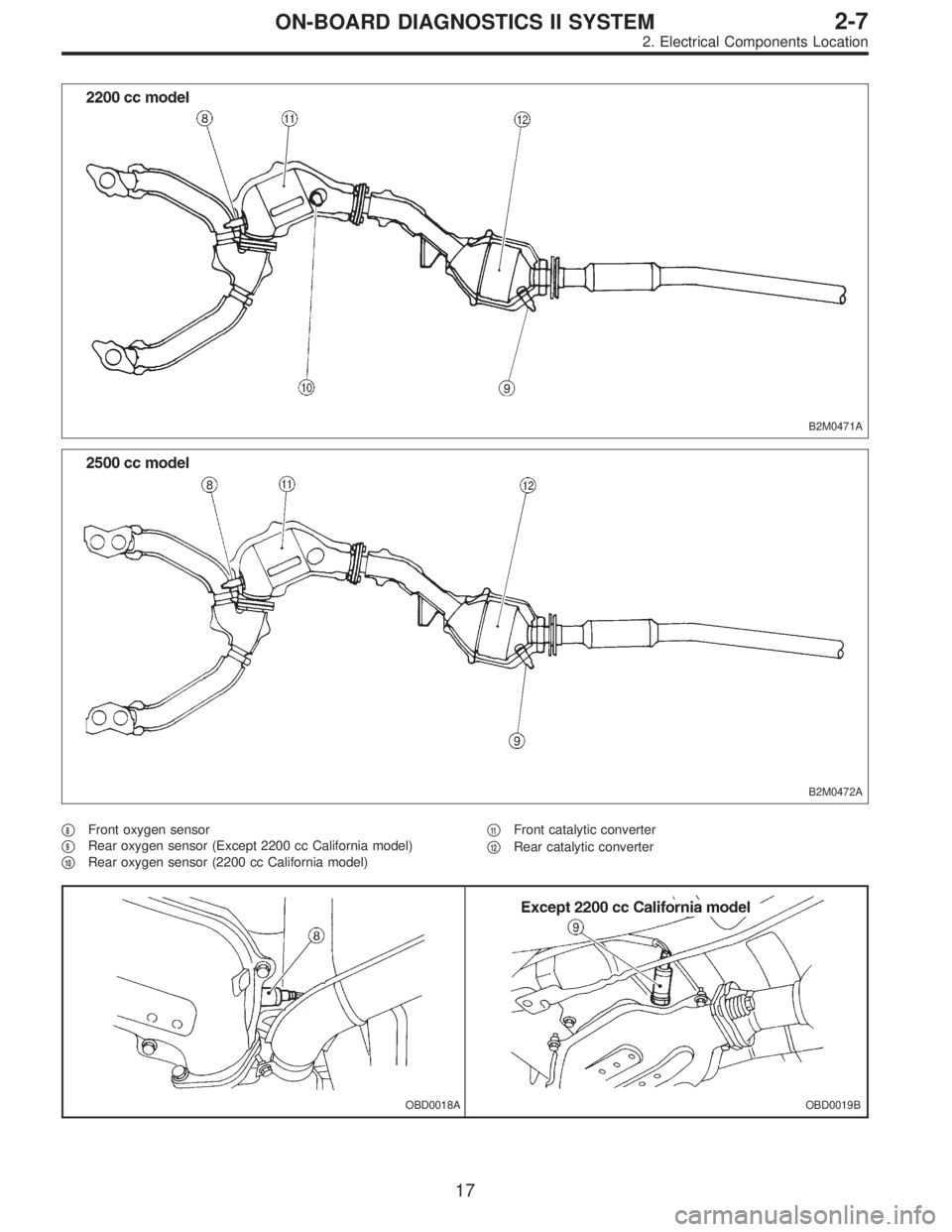
�8Front oxygen sensor
�
9Rear oxygen sensor (Except 2200 cc California model)
�
10Rear oxygen sensor (2200 cc California model)�
11Front catalytic converter
�
12Rear catalytic converter
OBD0018AOBD0019B
17
2-7ON-BOARD DIAGNOSTICS II SYSTEM
2. Electrical Components Location
Page 1787 of 2890
OBD0003C
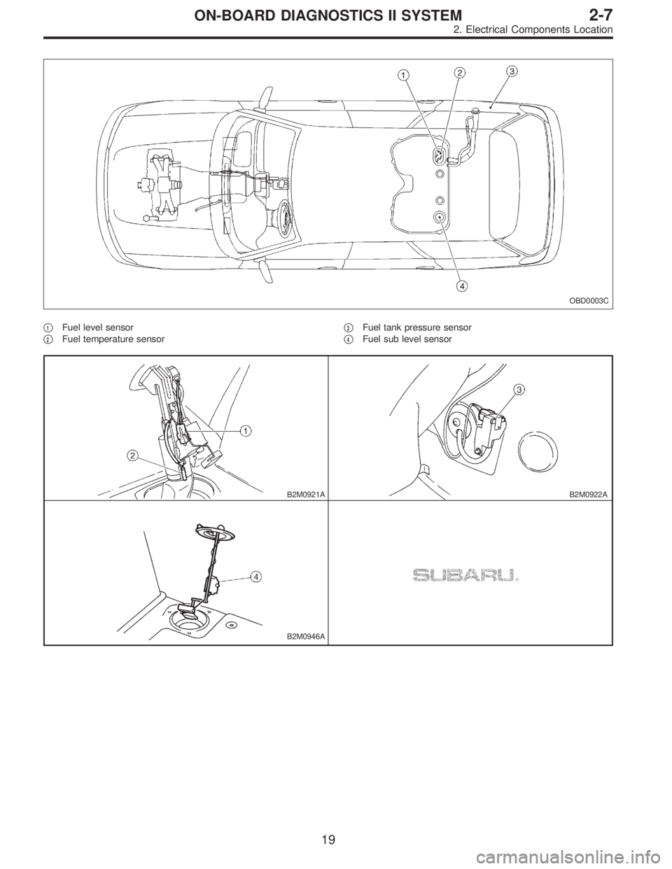
�1Fuel level sensor
�
2Fuel temperature sensor�
3Fuel tank pressure sensor
�
4Fuel sub level sensor
B2M0921AB2M0922A
B2M0946A
19
2-7ON-BOARD DIAGNOSTICS II SYSTEM
2. Electrical Components Location
Page 1793 of 2890
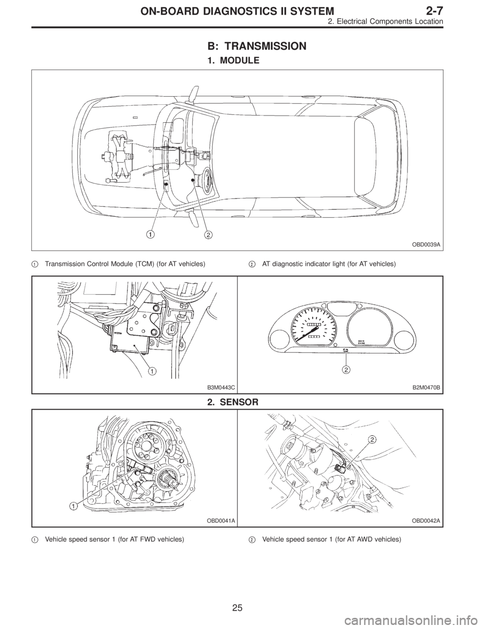
B: TRANSMISSION
1. MODULE
OBD0039A
�1Transmission Control Module (TCM) (for AT vehicles)�2AT diagnostic indicator light (for AT vehicles)
B3M0443CB2M0470B
2. SENSOR
OBD0041AOBD0042A
�1Vehicle speed sensor 1 (for AT FWD vehicles)�2Vehicle speed sensor 1 (for AT AWD vehicles)
25
2-7ON-BOARD DIAGNOSTICS II SYSTEM
2. Electrical Components Location
Page 1794 of 2890
OBD0043AOBD0044A
H2M1145BOBD0653A
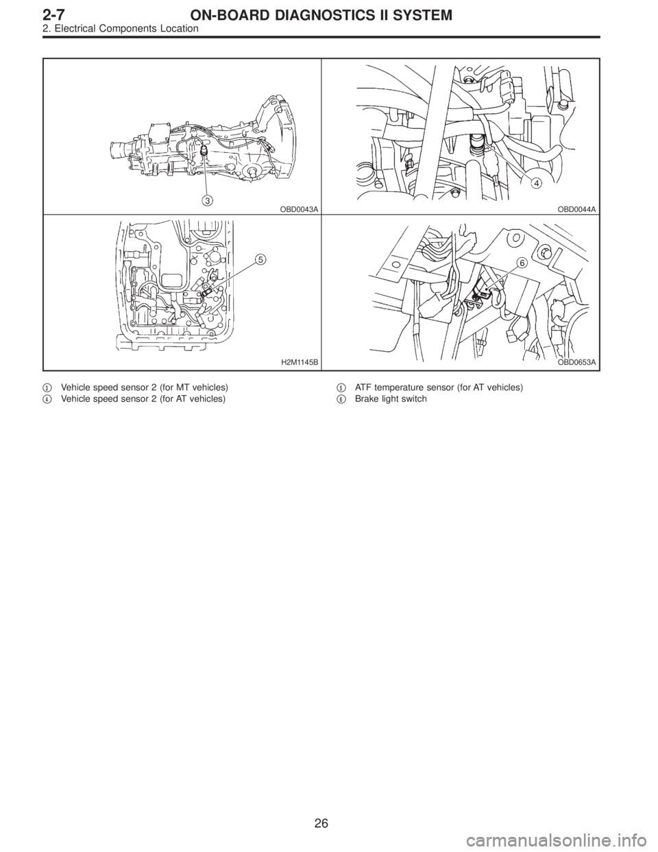
�3Vehicle speed sensor 2 (for MT vehicles)
�
4Vehicle speed sensor 2 (for AT vehicles)�
5ATF temperature sensor (for AT vehicles)
�
6Brake light switch
26
2-7ON-BOARD DIAGNOSTICS II SYSTEM
2. Electrical Components Location
Page 1797 of 2890
 Prepare a general scan tool (OBD-II general scan tool)
required by SAE J1978.
2) Open the cover and connect the OBD-II ge")
OBD0006C
B: OBD-II GENERAL SCAN TOOL
1. HOW TO USE OBD-II GENERAL SCAN TOOL
1) Prepare a general scan tool (OBD-II general scan tool)
required by SAE J1978.
2) Open the cover and connect the OBD-II general scan
tool to the data link connector located in the lower portion
of the instrument panel (on the driver’s side), to the lower
cover.
3) Using the OBD-II general scan tool, call up diagnostic
trouble code(s) and freeze frame data.
OBD-II general scan tool functions consist of:
(1) MODE $01: Current powertrain diagnostic data
(2) MODE $02: Powertrain freeze frame data
(3) MODE $03: Emission-related powertrain diagnostic
trouble codes
(4) MODE $04: Clear/Reset emission-related diagnos-
tic information
(5) MODE $05: Oxygen sensor monitoring test results
Read out data according to repair procedures.
(For detailed operation procedures, refer to the OBD-II
General Scan Tool Operation Manual.)
NOTE:
For details concerning diagnostic trouble codes, refer to
the DIAGNOSTIC TROUBLE CODE (DTC) LIST, 2-7
[T10A0].
H2M1280
2. DATA LINK CONNECTOR (FOR OBD-II GENERAL
SCAN TOOL AND SUBARU SELECT MONITOR)
1) This connector is used both for OBD-II general scan
tools and the Subaru Select Monitor.
2) Terminal No. 4 to No. 6 of the data link connector is
used for the Subaru Select Monitor signal.
CAUTION:
Do not connect any scan tools other than the OBD-II
general scan tools and the Subaru Select Monitor,
because the circuit for the Subaru Select Monitor may
be damaged.
Terminal No. Contents Terminal No. Contents
1 Power supply 9 Blank
2 Blank 10 K line of ISO 9141 CARB
3 Blank 11 Blank
4Subaru Select Monitor signal (ECM to Subaru
Select Monitor)*12 Ground
5Subaru Select Monitor signal (Subaru Select
Monitor to ECM)*13 Ground
6 Subaru Select Monitor clock* 14 Blank
7 Blank 15 Blank
8 Blank 16 Blank
*: Circuit only for Subaru Select Monitor
29
2-7ON-BOARD DIAGNOSTICS II SYSTEM
3. Diagnosis System
Page 1798 of 2890

Refers to data denoting the current operating condition of
analog input/output, digital input/output and/or the power-
train system.
A list of the supp")
3. CURRENT POWERTRAIN DIAGNOSTIC DATA
(MODE $01)
Refers to data denoting the current operating condition of
analog input/output, digital input/output and/or the power-
train system.
A list of the support data and PID (Parameter Identification)
codes are shown in the following table.
PID DataUnit of measure
01 Number of emission-related powertrain trouble codes and MIL status ON/OFF
03 Fuel system control status—
04 Calculated engine load value%
05 Engine coolant temperature°C
06 Short term fuel trim%
07 Long term fuel trim%
0B Intake manifold absolute pressurekPa
0C Engine revolutionrpm
0D Vehicle speedkm/h
0E Ignition timing advance°
10 Air flow rate from mass air flow sensor g/sec
11 Throttle valve opening angle%
13 Check whether oxygen sensor is installed.—
14 Oxygen sensor output voltage and short term fuel trim associated with oxygen sensor—bank 1 V and %
15 Oxygen sensor output voltage and short term fuel trim associated with oxygen sensor—bank 2 V and %
1C On-board diagnosis system—
NOTE:
Refer to OBD-II general scan tool manufacturer’s instruc-
tion manual to access generic OBD-II PIDs (MODE $01).
4. POWERTRAIN FREEZE FRAME DATA (MODE $02)
Refers to data denoting the operating condition when
trouble is sensed by the on-board diagnosis system.
A list of the support data and PID (Parameter Identification)
codes are shown in the following table.
PID DataUnit of measure
02 Trouble code that caused CARB required freeze frame data storage—
03 Fuel system control status—
04 Calculated engine load value%
05 Engine coolant temperature°C
06 Short term fuel trim%
07 Long term fuel trim%
0B Intake manifold absolute pressurekPa
0C Engine revolutionrpm
0D Vehicle speedkm/h
NOTE:
Refer to OBD-II general scan tool manufacturer’s instruc-
tion manual to access freeze frame data (MODE $02).
30
2-7ON-BOARD DIAGNOSTICS II SYSTEM
3. Diagnosis System
 and the hydraulic")