Page 1799 of 2890

Refers to data denoting emission-related powertrain diag-
nostic trouble codes.
For details concerning diagnostic trouble codes, refer")
5. EMISSION-RELATED POWERTRAIN DIAGNOSTIC
TROUBLE CODE (MODE $03)
Refers to data denoting emission-related powertrain diag-
nostic trouble codes.
For details concerning diagnostic trouble codes, refer to
the DIAGNOSTIC TROUBLE CODE (DTC) LIST, 2-7
[T10A0].
NOTE:
Refer to OBD-II general scan tool manufacturer’s instruc-
tion manual to access emission-related powertrain diag-
nostic trouble codes (MODE $03).
6. CLEAR/RESET EMISSION-RELATED DIAGNOSTIC
INFORMATION (MODE $04)
Refers to the mode used to clear or reset emission-related
diagnostic information (OBD-II trouble diagnostic informa-
tion).
NOTE:
Refer to OBD-II general scan tool manufacturer’s instruc-
tion manual to clear or reset emission-related diagnostic
information (MODE $04).
7. OXYGEN SENSOR MONITORING TEST RESULTS
(MODE $05)
Refers to the mode using oxygen sensor output data while
the on-board diagnosis system is performing diagnosis on
the oxygen sensor.
A list of the support oxygen sensor output data and test ID
(identification) are shown in the following table.
Test ID DataUnit of measure
01 Rich to lean sensor threshold voltage (constant) V
02 Lean to rich sensor threshold voltage (constant) V
03 Low sensor voltage for switch time calculation (constant) V
04 High sensor voltage for switch time calculation (constant) V
05 Rich to lean sensor switch time (calculated) sec.
06 Lean to rich sensor switch time (calculated) sec.
07 Minimum sensor voltage for test cycle (calculated) V
08 Maximum sensor voltage for test cycle (calculated) V
NOTE:
Refer to OBD-II general scan tool manufacturer’s instruc-
tion manual to access oxygen sensor monitoring test
results (MODE $05).
31
2-7ON-BOARD DIAGNOSTICS II SYSTEM
3. Diagnosis System
Page 1805 of 2890

6. READ DATA FUNCTION KEY LIST FOR ENGINE
Function mode Contents Abbreviation Unit of measure
F00 ROM ID number YEAR—
F01 Battery voltage VB V
F02 Vehicle speed signal VSP km/h, MPH
F03 Engine speed signal EREV rpm
F04 Engine coolant temperature signal TW°C,°F
F05 Ignition signal ADVS deg
F06 Mass air flow signal QA g/s, V
F07 Throttle position signal THV %, V
F08 Injector pulse width TIM mS
F09 Idle air control signal ISC %
F10 Load data LOAD %
F11 Front oxygen sensor output signal O2 V
F12 Front oxygen sensor maximum and minimum output signal O2max - min V, V
F13 Rear oxygen sensor output signal RO2 V
F14 Rear oxygen sensor maximum and minimum output signal RO2max - min V, V
F17 Short term fuel trim ALPHA %
F19 Knock sensor signal KNOCK deg
F20 Atmospheric absolute pressure signal BARO. P kPa, mmHg
F21 Intake manifold absolute pressure signal MANI. P kPa, mmHg
F29 A/F correction (short term trim) by rear oxygen sensor PHOS %
F30 Long term fuel trim KBLRC %
F31 Long term whole fuel trim K0 %
F32 Front oxygen sensor heater current FO2H A
F33 Rear oxygen sensor heater current RO2H A
F35 Purge control solenoid valve duty ratio CPCD %
F36Maximum value of cylinder #1 misfire times during 100 rota-
tionsMF1 %
F37Maximum value of cylinder #2 misfire times during 100 rota-
tionsMF2 %
F38Maximum value of cylinder #3 misfire times during 100 rota-
tionsMF3 %
F39Maximum value of cylinder #4 misfire times during 100 rota-
tionsMF4 %
F42Maximum and minimum EGR system pressure value (AT
vehicles only)EGRmax - min kPa
F43 Fuel tank pressure signal TNKP kPa, mmHg
F44 Fuel temperature signal TNKT°C,°F
F45 Fuel level signal FLEVEL V
FA 0 O N)OFF signal——
FA 1 O N)OFF signal——
FA 2 O N)OFF signal——
FA 3 O N)OFF signal——
FA 4 O N)OFF signal——
FA 5 O N)OFF signal——
FB0 Diagnostic trouble code (DTC) INSPECT—
FB1 Diagnostic trouble code (DTC) OBD—
37
2-7ON-BOARD DIAGNOSTICS II SYSTEM
3. Diagnosis System
Page 1809 of 2890
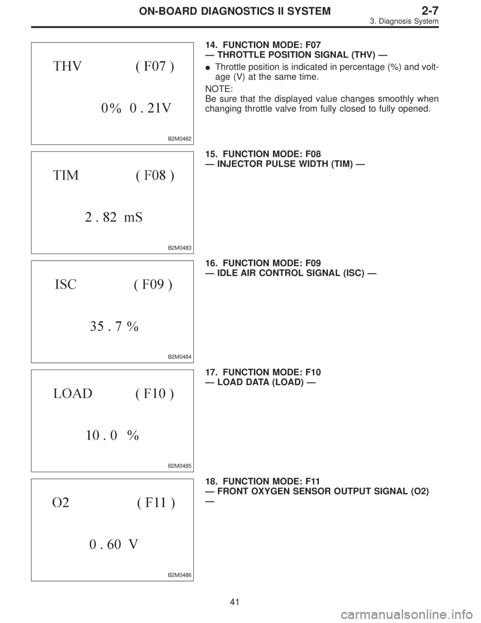
B2M0482
14. FUNCTION MODE: F07
—THROTTLE POSITION SIGNAL (THV)—
�Throttle position is indicated in percentage (%) and volt-
age (V) at the same time.
NOTE:
Be sure that the displayed value changes smoothly when
changing throttle valve from fully closed to fully opened.
B2M0483
15. FUNCTION MODE: F08
—INJECTOR PULSE WIDTH (TIM)—
B2M0484
16. FUNCTION MODE: F09
—IDLE AIR CONTROL SIGNAL (ISC)—
B2M0485
17. FUNCTION MODE: F10
—LOAD DATA (LOAD)—
B2M0486
18. FUNCTION MODE: F11
—FRONT OXYGEN SENSOR OUTPUT SIGNAL (O2)
—
41
2-7ON-BOARD DIAGNOSTICS II SYSTEM
3. Diagnosis System
Page 1810 of 2890
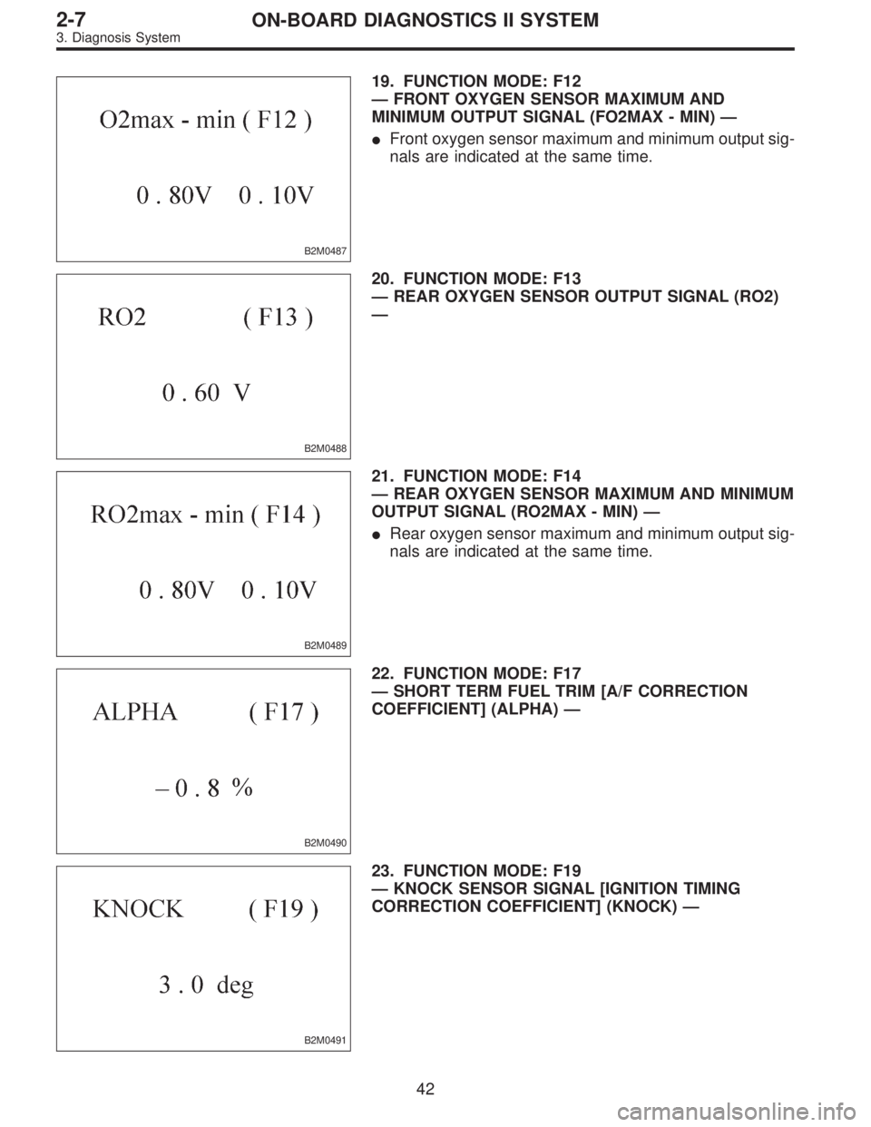
B2M0487
19. FUNCTION MODE: F12
—FRONT OXYGEN SENSOR MAXIMUM AND
MINIMUM OUTPUT SIGNAL (FO2MAX - MIN)—
�Front oxygen sensor maximum and minimum output sig-
nals are indicated at the same time.
B2M0488
20. FUNCTION MODE: F13
—REAR OXYGEN SENSOR OUTPUT SIGNAL (RO2)
—
B2M0489
21. FUNCTION MODE: F14
—REAR OXYGEN SENSOR MAXIMUM AND MINIMUM
OUTPUT SIGNAL (RO2MAX - MIN)—
�Rear oxygen sensor maximum and minimum output sig-
nals are indicated at the same time.
B2M0490
22. FUNCTION MODE: F17
—SHORT TERM FUEL TRIM [A/F CORRECTION
COEFFICIENT] (ALPHA)—
B2M0491
23. FUNCTION MODE: F19
—KNOCK SENSOR SIGNAL [IGNITION TIMING
CORRECTION COEFFICIENT] (KNOCK)—
42
2-7ON-BOARD DIAGNOSTICS II SYSTEM
3. Diagnosis System
Page 1811 of 2890
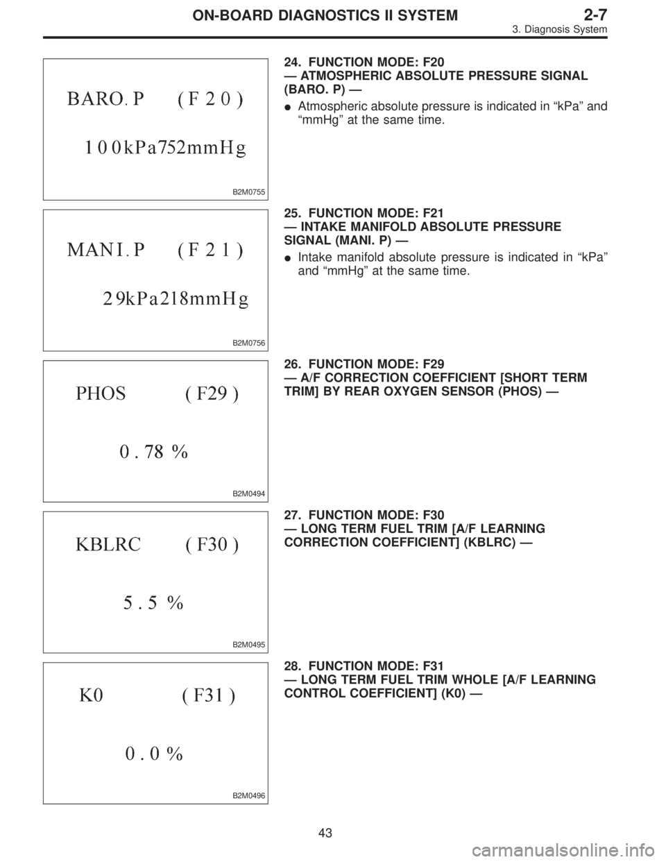
B2M0755
24. FUNCTION MODE: F20
—ATMOSPHERIC ABSOLUTE PRESSURE SIGNAL
(BARO. P)—
�Atmospheric absolute pressure is indicated in“kPa”and
“mmHg”at the same time.
B2M0756
25. FUNCTION MODE: F21
—INTAKE MANIFOLD ABSOLUTE PRESSURE
SIGNAL (MANI. P)—
�Intake manifold absolute pressure is indicated in“kPa”
and“mmHg”at the same time.
B2M0494
26. FUNCTION MODE: F29
—A/F CORRECTION COEFFICIENT [SHORT TERM
TRIM] BY REAR OXYGEN SENSOR (PHOS)—
B2M0495
27. FUNCTION MODE: F30
—LONG TERM FUEL TRIM [A/F LEARNING
CORRECTION COEFFICIENT] (KBLRC)—
B2M0496
28. FUNCTION MODE: F31
—LONG TERM FUEL TRIM WHOLE [A/F LEARNING
CONTROL COEFFICIENT] (K0)—
43
2-7ON-BOARD DIAGNOSTICS II SYSTEM
3. Diagnosis System
Page 1812 of 2890
B2M0497
29. FUNCTION MODE: F32
—FRONT OXYGEN SENSOR HEATER CURRENT
(FO2H)—
B2M0498
30. FUNCTION MODE: F33
—REAR OXYGEN SENSOR HEATER CURRENT
(RO2H)—
H2M1325
31. FUNCTION MODE: F35
—PURGE CONTROL SOLENOID VALVE DUTY RATIO
(CPCD)—
B2M0499
32. FUNCTION MODE: F36
—MAXIMUM VALUE OF CYLINDER #1 MISFIRE RATE
DURING 100 ROTATIONS (MF1)—
B2M0500
33. FUNCTION MODE: F37
—MAXIMUM VALUE OF CYLINDER #2 MISFIRE RATE
DURING 100 ROTATIONS (MF2)—
44
2-7ON-BOARD DIAGNOSTICS II SYSTEM
3. Diagnosis System
Page 1814 of 2890
—
40. FA MODE FOR ENGINE
Function
modeLED No. Contents Display LED“ON”requirements
FA 03 Neutral switch NT When neutral position signa")
H2M1327
39. FUNCTION MODE: F45
—FUEL LEVEL SIGNAL (FLEVEL)—
40. FA MODE FOR ENGINE
Function
modeLED No. Contents Display LED“ON”requirements
FA 03 Neutral switch NT When neutral position signal is entered.
7 Test mode connector UD When test mode connector is connected.
8 AT/MT identification signal AT When AT identification signal is entered.
9 Ignition switch IG When ignition switch is turned ON.
FA 11 Radiator fan relay 2 R2 When radiator fan relay 2 is in function.
2 Knock signal KS When knock signal is entered.
3 Purge control solenoid valve CN When purge control solenoid valve is in function.
4 Fuel pump relay FP When fuel pump relay is in function.
6 Radiator fan relay 1 R1 When radiator fan relay 1 is in function.
7 Air conditioner relay AR When air conditioner relay is in function.
8 Air conditioner switch AC When air conditioner switch is turned ON.
FA 22 AEC signal EC When AEC signal is entered.
3 EAM signal AM When EAM signal is gone out.
4 AEB signal EB When AEB signal is entered.
6 AET signal ET When AET signal is entered.
7 Engine torque control signal TR When engine torque control signal is entered.
FA3 7 Pressure sources switching solenoid valve BRWhen pressure sources switching solenoid valve
is in function.
FA 41 Catalyst CA When diagnosis of catalyzer is finished.
2 EGR system E1 When diagnosis of EGR system is finished.
3 California model identification signal FCWhen California model identification signal is
entered.
8 Rear oxygen sensor signal OR When rear oxygen sensor mixture ratio is rich.
9 Front oxygen sensor signal O2 When front oxygen sensor mixture ratio is rich.
FA 56 Vent control solenoid valve AL When vent control solenoid valve is in function.
7 EGR solenoid valve ER When EGR solenoid valve is in function.
8 Pressure control solenoid valve PCWhen pressure control solenoid valve is in
function.
46
2-7ON-BOARD DIAGNOSTICS II SYSTEM
3. Diagnosis System
Page 1817 of 2890

LED No. Signal name Display
1 Catalyst CA
2 EGR system E1
3California model
identification signalFC
4——
5——
6——
7——
8 Rear oxygen sensor signal OR
9 Front oxygen sensor signal O2
0——
CA E1 FC——
——OR O2—
1
2345
67890
45. FUNCTION MODE: FA4
—ON↔OFF SIGNAL—
Requirement for LED“ON”.
LED No. 1 Diagnosis of catalyzer is finished.
LED No. 2 Diagnosis of EGR system is finished.
LED No. 3 Vehicle is except California model.
LED No. 8 Rear oxygen sensor mixture ratio is rich.
LED No. 9 Front oxygen sensor mixture ratio is rich.
LED No. Signal name Display
1——
2——
3——
4——
5——
6 Vent control solenoid valve AL
7 EGR solenoid valve ER
8Pressure control solenoid
valvePC
9——
0——
—————
AL ER PC——
1
2345
67890
46. FUNCTION MODE: FA5
—ON↔OFF SIGNAL—
Requirement for LED“ON”.
LED No. 6 Vent control solenoid valve is in function.
LED No. 7 EGR solenoid valve is in function.
LED No. 8 Pressure control solenoid valve is in func-
tion.
NOTE:
When LED No. 6, 7 and 8 blinks with the test mode con-
nector connected and the ignition switch turned to ON, the
corresponding part is functioning properly.
49
2-7ON-BOARD DIAGNOSTICS II SYSTEM
3. Diagnosis System
—
B2M0498
30. FUNCTION MODE: F33
—REAR OXYGEN SENSOR HEATER CURRENT
(RO2H)—
H2M1325
31. FUNCTION MODE: F35
—PURGE CON")