Page 975 of 2890
2. SIDE OIL SEAL
1) Disconnect ground cable from battery.
2) Move selector lever or gear shift lever to“N”.
3) Release the parking brake.
4) Loosen both wheel nuts.
5) Jack-up the vehicle and support it with rigid racks.
6) Remove wheels.
7) Remove rear exhaust pipe and muffler.
G3M0038
8) Remove the DOJ of rear drive shaft from rear differen-
tial.
(1) Remove the A.B.S. sensor cable clamp and park-
ing brake cable clamp from bracket.
G3M0039
(2) Remove the A.B.S. sensor cable clamp from the
trailing link.
G3M0040
(3) Remove the A.B.S. sensor cable clamp and park-
ing brake cable guide from the trailing link.
G3M0041
(4) Remove the rear stabilizer link.
16
3-4SERVICE PROCEDURE
2. Rear Differential
Page 1023 of 2890
G4M0504
4) Remove brake hose clamp and disconnect brake hose
from strut. Attach brake hose to body using gum tape.
5) Scribe an alignment mark on the camber adjusting bolt
which secures strut to housing.
6) Remove bolt securing the A.B.S. sensor harness.
(A.B.S. equipped models.)
G4M0505
7) Remove two bolts securing housing to strut.
CAUTION:
While holding head of adjusting bolt, loosen self-lock-
ing nut.
8) Remove the three nuts securing strut mount to body.
G4M0506
B: DISASSEMBLY
1) Using a coil spring compressor, compress coil spring.
G4M0507
2) Using ST, remove self-locking nut.
ST 927760000 STRUT MOUNT SOCKET
3) Remove strut mount, upper spring seat and rubber seat
from strut.
4) Gradually decreasing compression force of spring
compressor, and remove coil spring.
5) Remove dust cover and helper.
22
4-1SERVICE PROCEDURE
4. Front Strut
Page 1026 of 2890
 Pull the piston rod fully upward, and install rubber seat
and spring seat.
NOTE:
Ensure that upper spring seat is positioned with“OUT”
mark facing outward.
8) Install strut mount to the")
G4M0511
7) Pull the piston rod fully upward, and install rubber seat
and spring seat.
NOTE:
Ensure that upper spring seat is positioned with“OUT”
mark facing outward.
8) Install strut mount to the piston rod, and tighten the
self-locking nut temporarily.
CAUTION:
Be sure to use a new self-locking nut.
G4M0507
9) Using hexagon wrench to prevent strut rod from turning,
tighten self-locking nut with ST.
Tightening torque:
54±5 N⋅m (5.5±0.5 kg-m, 39.8±3.6 ft-lb)
ST 927760000 STRUT MOUNT SOCKET
10) Loosen the coil spring carefully.
E: INSTALLATION
1) Install strut mount at upper side of strut to body and
tighten with nuts.
Tightening torque:
20±6 N⋅m (2.0±0.6 kg-m, 14.5±4.3 ft-lb)
2) Connect housing to lower side of strut.
3) Position aligning mark on camber adjusting bolt with
aligning mark on lower side bracket of strut.
CAUTION:
�While holding head of adjusting bolt, tighten self-
locking nut.
�Be sure to use new self-locking nut.
Tightening torque:
152±20 N⋅m (15.5±2.0 kg-m, 112±14 ft-lb)
4) Install A.B.S. sensor harness to strut. (A.B.S. equipped
models.)
Tightening torque:
152±20 N⋅m (15.5±2.0 kg-m, 112±14 ft-lb)
5) Install brake hose at lower side of strut with clamp.
G4M0503
6) Install union bolts which secure brake caliper to brake
hose.
Tightening torque:
18±3 N⋅m (1.8±0.3 kg-m, 13.0±2.2 ft-lb)
CAUTION:
Be sure to bleed air from brake system.
7) Install wheels.
NOTE:
Check wheel alignment and adjust if necessary.
25
4-1SERVICE PROCEDURE
4. Front Strut
Page 1036 of 2890
 Loosen wheel nuts. Lift-up vehicle and remove wheel.
2) Remove rear exhaust pipe and muffler.
3) Remove stabilizer link from rear lateral link.
4) Scribe an aligning mark on ad")
G4M0529
1. FWD MODEL
1) Loosen wheel nuts. Lift-up vehicle and remove wheel.
2) Remove rear exhaust pipe and muffler.
3) Remove stabilizer link from rear lateral link.
4) Scribe an aligning mark on adjusting bolt, adjusting
wheel and crossmember.
5) Remove bolts securing lateral links to housing.
6) Turn cap (lateral link) counterclockwise until it contacts
stopper, then remove cap.
7) While holding adjusting bolt’s head with a wrench,
loosen self-locking nut.
CAUTION:
Always loosen self-locking nut before turning adjust-
ing bolt.
8) Lateral link removal
(1) Left lateral links
Remove adjusting bolt and front and rear lateral links.
(2) Right lateral links
Support crossmember with transmission jack.
Remove bolts securing crossmember to vehicle body.
Lower transmission jack until adjusting bolt can be
removed. Remove adjusting bolt, front and rear lateral
links.
2. AWD MODEL
1) Loosen wheel nuts. Lift-up vehicle and remove wheel.
2) Remove stabilizers link from lateral link.
3) Remove A.B.S. sensor harness from trailing link.
(A.B.S. equipped models.)
B4M0573A
4) Remove bolt securing trailing link to housing.
5) Remove DOJ from differential.
6) Scribe an alignment mark on rear lateral link adjusting
bolt and crossmember.
7) Remove bolt securing lateral link to housing.
8) Remove bolts securing front and rear lateral links to
crossmember, detach lateral links.
CAUTION:
To loosen adjusting bolt, always loosen nut while hold-
ing the head of adjusting bolt.
35
4-1SERVICE PROCEDURE
8. Lateral Link
Page 1043 of 2890
 Install strut mount cap.
2) Tighten self-locking nut used to secure strut mount to
vehicle body.
CAUTION:
Use a new self-locking nut.
NOTE:
Tighten strut mount and cap as a unit.
Ti")
E: INSTALLATION
1) Install strut mount cap.
2) Tighten self-locking nut used to secure strut mount to
vehicle body.
CAUTION:
Use a new self-locking nut.
NOTE:
Tighten strut mount and cap as a unit.
Tightening torque:
20±6 N⋅m (2.0±0.6 kg-m, 14.5±4.3 ft-lb)
3) Tighten bolts securing rear strut to housing.
Tightening torque:
196
+39
�10N⋅m (20.0+4.0
�1.0kg-m, 145+29
�7ft-lb)
CAUTION:
Use a new self-locking nut.
4) Models with rear disc brakes:
Tighten brake hose union bolt on brake caliper.
Tightening torque:
18±3 N⋅m (1.8±0.3 kg-m, 13.0±2.2 ft-lb)
Models with rear drum brakes:
Connect brake hose to brake pipe.
Tightening torque:
15
+3
�2N⋅m (1.5+0.3
�0.2kg-m, 10.8+2.2
�1.4ft-lb)
5) Insert brake hose clip between brake hose and lower
side of strut.
CAUTION:
�Check that hose clip is positioned properly.
�Check brake hose for twisting, or excessive tension.
�Models equipped with A.B.S.:
Do not subject A.B.S. sensor harness to excessive ten-
sion.
6) Be sure to bleed air from brake system.
7) Lower vehicle and tighten wheel nut.
Tightening torque:
88±10 N⋅m (9±1 kg-m, 65±7 ft-lb)
8) Sedan:
Install rear seat backrest and rear seat cushion.
Wagon:
Install strut cap of rear quarter trim.
NOTE:
Check wheel alignment and adjust if necessary.
42
4-1SERVICE PROCEDURE
9. Rear Strut
Page 1046 of 2890
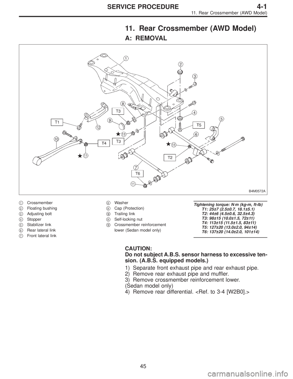
11. Rear Crossmember (AWD Model)
A: REMOVAL
B4M0572A
�1Crossmember
�
2Floating bushing
�
3Adjusting bolt
�
4Stopper
�
5Stabilizer link
�
6Rear lateral link
�
7Front lateral link�
8Washer
�
9Cap (Protection)
�
10Trailing link
�
11Self-locking nut
�
12Crossmember reinforcement
lower (Sedan model only)
Tightening torque: N⋅m (kg-m, ft-lb)
T1: 25±7 (2.5±0.7, 18.1±5.1)
T2: 44±6 (4.5±0.6, 32.5±4.3)
T3: 98±15 (10.0±1.5, 72±11)
T4: 113±15 (11.5±1.5, 83±11)
T5: 127±20 (13.0±2.0, 94±14)
T6: 137±20 (14.0±2.0, 101±14)
CAUTION:
Do not subject A.B.S. sensor harness to excessive ten-
sion. (A.B.S. equipped models.)
1) Separate front exhaust pipe and rear exhaust pipe.
2) Remove rear exhaust pipe and muffler.
3) Remove crossmember reinforcement lower.
(Sedan model only)
4) Remove rear differential.
45
4-1SERVICE PROCEDURE
11. Rear Crossmember (AWD Model)
Page 1057 of 2890
G4M0217
9) Remove disc rotor from hub.
If disc rotor seizes up within hub, drive disc rotor out by
installing an 8-mm bolt in screw hole on the rotor.
G4M0218
10) Remove cotter pin and castle nut which secure tie-rod
end to housing knuckle arm.
G4M0219
11) Using a puller, remove tie-rod ball joint from knuckle
arm.
G4M0220
12) On A.B.S. equipped models, remove A.B.S. sensor
assembly and harness in advance.
CAUTION:
Be sure to use soft jaws (such as aluminum plates)
when placing the mating surfaces of housing and strut
in a vise.
G4M0221
13) Remove transverse link ball joint from housing.
10
4-2SERVICE PROCEDURE
1. Front Axle
Page 1062 of 2890
 Install transverse link ball joint to housing.
Tightening torque:
44±6 N⋅m (4.5±0.6 kg-m, 32.5±4.3 ft-lb)
2) While aligning alignment mark on camber adjusting bolt
head, connec")
E: INSTALLATION
1) Install transverse link ball joint to housing.
Tightening torque:
44±6 N⋅m (4.5±0.6 kg-m, 32.5±4.3 ft-lb)
2) While aligning alignment mark on camber adjusting bolt
head, connect housing and strut.
CAUTION:
Use a new self-locking nut.
Tightening torque:
147±15 N⋅m (15±1.5 kg-m, 108±11 ft-lb)
3) Install speed sensor and harness on housing (only
vehicle equipped with A.B.S.).
4) Install disc rotor on hub.
5) Install disc brake caliper on housing.
Tightening torque:
59±10 N⋅m (6±1 kg-m, 43±7 ft-lb)
6) Install front drive shaft.
7) Connect stabilizer link.
G4M0236
8) Install tie-rod end ball joint on housing knuckle arm.
Tightening torque:
27.0±2.5 N⋅m (2.75±0.25 kg-m, 19.9±1.8 ft-lb)
G4M0237
9) While depressing brake pedal, tighten axle nut and lock
it securely.
Tightening torque:
186±20 N⋅m (19±2 kg-m, 137±14 ft-lb)
CAUTION:
�Use a new axle nut.
�Always tighten axle nut before installing wheel on
vehicle. If wheel is installed and comes in contact with
ground when axle nut is loose, wheel bearings may be
damaged.
�Be sure to tighten axle nut to specified torque. Do
not overtighten it as this may damage wheel bearing.
15
4-2SERVICE PROCEDURE
1. Front Axle
 Disconnect ground cable from battery.
2) Move selector lever or gear shift lever to“N”.
3) Release the parking brake.
4) Loosen both wheel nuts.
5) Jack-up the vehicle and supp")
 Remove brake hose clamp and disconnect brake hose
from strut. Attach brake hose to body using gum tape.
5) Scribe an alignment mark on the camber adjusting bolt
which secures strut to housi")
 Remove disc rotor from hub.
If disc rotor seizes up within hub, drive disc rotor out by
installing an 8-mm bolt in screw hole on the rotor.
G4M0218
10) Remove cotter pin and castle nut whic")