Page 648 of 2890
G2M0416
10. Camshaft Position Sensor
A: REMOVAL AND INSTALLATION
1) Disconnect connector from camshaft position sensor.
G2M0417
2) Remove camshaft position sensor from camshaft sup-
port LH.
3) Installation is in the reverse order of removal.
Tightening torque:
6.4±0.5 N⋅m (0.65±0.05 kg-m, 4.7±0.4 ft-lb)
B2M0355
11. Pressure Sensor (AT model)
A: REMOVAL AND INSTALLATION
1) Disconnect connector from pressure sensor.
2) Disconnect hose from pressure sensor.
B2M0356
3) Remove pressure sensor from bracket.
4) Installation is in the reverse order of removal.
Tightening torque:
6.4±0.5 N⋅m (0.65±0.05 kg-m, 4.7±0.4 ft-lb)
25
2-7SERVICE PROCEDURE
10. Camshaft Position Sensor - 11. Pressure Sensor (AT model)
Page 649 of 2890
G2M0416
10. Camshaft Position Sensor
A: REMOVAL AND INSTALLATION
1) Disconnect connector from camshaft position sensor.
G2M0417
2) Remove camshaft position sensor from camshaft sup-
port LH.
3) Installation is in the reverse order of removal.
Tightening torque:
6.4±0.5 N⋅m (0.65±0.05 kg-m, 4.7±0.4 ft-lb)
B2M0355
11. Pressure Sensor (AT model)
A: REMOVAL AND INSTALLATION
1) Disconnect connector from pressure sensor.
2) Disconnect hose from pressure sensor.
B2M0356
3) Remove pressure sensor from bracket.
4) Installation is in the reverse order of removal.
Tightening torque:
6.4±0.5 N⋅m (0.65±0.05 kg-m, 4.7±0.4 ft-lb)
25
2-7SERVICE PROCEDURE
10. Camshaft Position Sensor - 11. Pressure Sensor (AT model)
Page 666 of 2890

�1Clamp
�
2Fuel delivery hose A
�
3Fuel filter bracket
�
4Fuel filter holder
�
5Fuel filter cup
�
6Fuel filter
�
7Evaporation hose
�
8Clip
�
9Fuel delivery hose B
�
10Fuel return hose
�
11Roll over valve
�
12Roll over valve bracket
�
13Evaporation hose H
�
14Evaporation hose I
�
15Evaporation pipe B
�
16Canister hose A
�
17Canister hose B
�
18Canister holder
�
19Canister upper bracket
�
20Cushion rubber
�
21Canister lower bracket
�
22Canister
�
23Fuel pipe ASSY
�
24Fuel filler valve
�
25Fuel filler pipe
�
26Packing�
27Ring A
�
28Ring B
�
29Fuel filler cap
�
30Fuel filler pipe protector
�
31Fuel tank pressure sensor
�
32Fuel tank pressure sensor hose A
�
33Fuel tank pressure sensor bracket
�
34Grommet
�
35Fuel tank pressure sensor hose B
�
36Air ventilator hose A
�
37Air ventilator pipe A
�
38Air ventilator hose B
�
39Air ventilator pipe B
�
40Air ventilator pipe protector
�
41Vent control solenoid valve
�
42Vent control solenoid valve hose
�
43Air filter hose A
�
44Air filter hose B
�
45Air filter
�
46Tapping screw
Tightening torque: N⋅m (kg-m, ft-lb)
T1: 23±7 (2.3±0.7, 17±5.1)
T2: 25±7 (2.5±0.7, 18±5.1)
9
2-8COMPONENT PARTS
2. Fuel Line
Page 692 of 2890
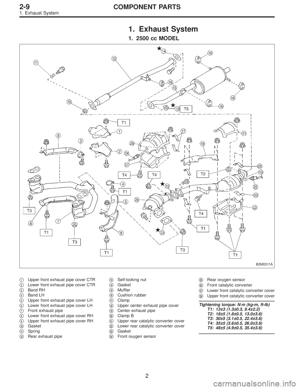
1. Exhaust System
1. 2500 cc MODEL
B2M0311A
�1Upper front exhaust pipe cover CTR
�
2Lower front exhaust pipe cover CTR
�
3Band RH
�
4Band LH
�
5Upper front exhaust pipe cover LH
�
6Lower front exhaust pipe cover LH
�
7Front exhaust pipe
�
8Lower front exhaust pipe cover RH
�
9Upper front exhaust pipe cover RH
�
10Gasket
�
11Spring
�
12Rear exhaust pipe�
13Self-locking nut
�
14Gasket
�
15Muffler
�
16Cushion rubber
�
17Clamp
�
18Upper center exhaust pipe cover
�
19Center exhaust pipe
�
20Clamp B
�
21Upper rear catalytic converter cover
�
22Lower rear catalytic converter cover
�
23Gasket
�
24Front oxygen sensor�
25Rear oxygen sensor
�
26Front catalytic converter
�
27Lower front catalytic converter cover
�
28Upper front catalytic converter cover
Tightening torque: N⋅m (kg-m, ft-lb)
T1: 13±3 (1.3±0.3, 9.4±2.2)
T2: 18±5 (1.8±0.5, 13.0±3.6)
T3: 30±5 (3.1±0.5, 22.4±3.6)
T4: 35±5 (3.6±0.5, 26.0±3.6)
T5: 48±5 (4.9±0.5, 35.4±3.6)
2
2-9COMPONENT PARTS
1. Exhaust System
Page 693 of 2890

2. 2200 cc MODEL
B2M0723A
�1Upper front exhaust pipe cover CTR
�
2Lower front exhaust pipe cover CTR
�
3Band RH
�
4Band LH
�
5Upper front exhaust pipe cover LH
�
6Lower front exhaust pipe cover LH
�
7Front exhaust pipe
�
8Lower front exhaust pipe cover RH
�
9Upper front exhaust pipe cover RH
�
10Gasket
�
11Spring
�
12Rear exhaust pipe
�
13Self-locking nut�
14Gasket
�
15Muffler
�
16Cushion rubber
�
17Clamp
�
18Upper center exhaust pipe cover
�
19Center exhaust pipe
�
20Clamp B
�
21Upper rear catalytic converter cover
�
22Lower rear catalytic converter cover
�
23Gasket
�
24Front oxygen sensor
�
25Rear oxygen sensor (California 2200
cc model)�
26Rear oxygen sensor (Except Califor-
nia 2200 cc model)
�
27Front catalytic converter
�
28Lower front catalytic converter cover
�
29Upper front catalytic converter cover
Tightening torque: N⋅m (kg-m, ft-lb)
T1: 13±3 (1.3±0.3, 9.4±2.2)
T2: 18±5 (1.8±0.5, 13.0±3.6)
T3: 30±5 (3.1±0.5, 22.4±3.6)
T4: 35±5 (3.6±0.5, 26.0±3.6)
T5: 48±5 (4.9±0.5, 35.4±3.6)
3
2-9COMPONENT PARTS
1. Exhaust System
Page 694 of 2890
B2M0724
1. Front Exhaust Pipe and Center
Exhaust Pipe
A: REMOVAL
1) Disconnect front oxygen sensor connector.
B2M0725
2) Disconnect rear oxygen sensor connector. (California
2200 cc model)
B2M0312
3) Lift-up the vehicle.
4) Disconnect rear oxygen sensor connector. (Except Cali-
fornia 2200 cc model)
B2M0055
5) Separate center exhaust pipe from rear exhaust pipe.
B2M0054
6) Remove bolts which hold front exhaust pipe onto cylin-
der heads.
4
2-9SERVICE PROCEDURE
1. Front Exhaust Pipe and Center Exhaust Pipe
Page 696 of 2890
B2M0055
4) Install center exhaust pipe to rear exhaust pipe.
Tightening torque:
18±5 N⋅m (1.8±0.5 kg-m, 13.0±3.6 ft-lb)
B2M0313
5) Tighten bolt which holds center exhaust pipe to hanger
bracket.
Tightening torque:
35±5 N⋅m (3.6±0.5 kg-m, 26.0±3.6 ft-lb)
B2M0312
6) Connect rear oxygen sensor connector. (Except Califor-
nia 2200 cc model)
B2M0725
7) Lower the vehicle.
8) Connect rear oxygen sensor connector. (California
2200 cc model)
B2M0724
9) Connect front oxygen sensor connector.
6
2-9SERVICE PROCEDURE
1. Front Exhaust Pipe and Center Exhaust Pipe
Page 724 of 2890
G2M0270
(3) Disconnect A/C pressure hoses from A/C compres-
sor.
G2M0271
8) Remove air intake system.
(1) Disconnect connector from mass air flow sensor.
(2) Remove air intake duct with air cleaner upper
cover, and remove air cleaner element.
G2M0272
9) Remove canister and bracket.
11
2-11SERVICE PROCEDURE
2. Engine
 Disconnect connector from camshaft position sensor.
G2M0417
2) Remove camshaft position sensor from camshaft sup-
port LH.
3) Instal")
 Disconnect connector from camshaft position sensor.
G2M0417
2) Remove camshaft position sensor from camshaft sup-
port LH.
3) Instal")
 Disconnect front oxygen sensor connector.
B2M0725
2) Disconnect rear oxygen sensor connector. (California
2200 cc model)
B2M0312
3)")
 Install center exhaust pipe to rear exhaust pipe.
Tightening torque:
18±5 N⋅m (1.8±0.5 kg-m, 13.0±3.6 ft-lb)
B2M0313
5) Tighten bolt which holds center exhaust pipe to hanger
bracket.")
 Disconnect A/C pressure hoses from A/C compres-
sor.
G2M0271
8) Remove air intake system.
(1) Disconnect connector from mass air flow sensor.
(2) Remove air intake duct with air cleaner up")