Page 725 of 2890
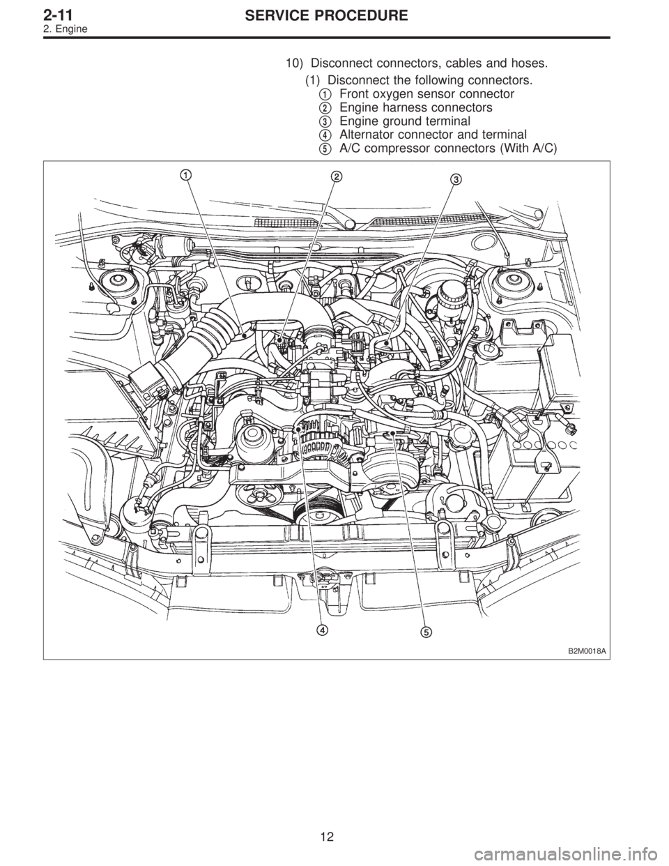
10) Disconnect connectors, cables and hoses.
(1) Disconnect the following connectors.
�
1Front oxygen sensor connector
�
2Engine harness connectors
�
3Engine ground terminal
�
4Alternator connector and terminal
�
5A/C compressor connectors (With A/C)
B2M0018A
12
2-11SERVICE PROCEDURE
2. Engine
Page 730 of 2890
B2M0335
(3) Disconnect connector from rear oxygen sensor.
G2M0291
(4) Separate center exhaust pipe from rear exhaust
pipe.
B2M0313
(5) Remove bolt which installs center exhaust pipe on
hunger bracket.
(6) Take off front and center exhaust pipes.
CAUTION:
Exhaust pipe will drop when all bolts are removed. So,
hold it when removing the last bolt.
G2M0292
13) Remove nuts which hold lower side of transmission to
engine.
G2M0293
14) Remove nuts which install front cushion rubber onto
front crossmember.
17
2-11SERVICE PROCEDURE
2. Engine
Page 737 of 2890
11) Install front exhaust pipe and center exhaust pipe.
12) Connect hoses, connectors and cables.
(1) Connect the following hoses.
�Fuel delivery hose, return hose and evaporation
hose
�Heater inlet and outlet hoses
�Brake booster vacuum hose
(2) Connect the following connectors.
�Engine ground terminal
�Engine harness connectors
�Front oxygen sensor connector
�Rear oxygen sensor connector
�Alternator connector and terminal
�A/C compressor connectors (With A/C)
(3) Connect the following cables.
�Accelerator cable
�Cruise control cables (With cruise control)
�Clutch cable
�Clutch release spring
CAUTION:
After connecting each cable, adjust them.
G2M0271
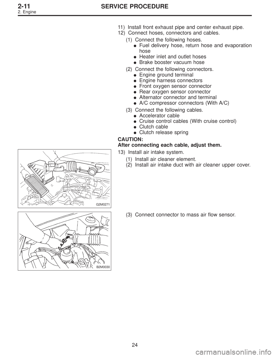
13) Install air intake system.
(1) Install air cleaner element.
(2) Install air intake duct with air cleaner upper cover.
B2M0030
(3) Connect connector to mass air flow sensor.
24
2-11SERVICE PROCEDURE
2. Engine
Page 742 of 2890
G2M0266
1) Open front hood fully, and support with stay.
2) Disconnect battery ground terminal.
3) Remove air intake duct.
G2M0544
4) Disconnect connectors and cables.
(1) Disconnect the following connectors.
�Front oxygen sensor connector
G2M0307
�Transmission harness connector
�Transmission ground terminal
B2M0337
�Neutral position switch connector (MT model)
�Back-up light switch connector (MT model)
G2M0827
�Vehicle speed sensor 2
29
2-11SERVICE PROCEDURE
3. Transmission
Page 744 of 2890
G2M0312
9) Remove transmission connector holder bracket.
G2M0313
10) Set ST.
ST 41099AA020 ENGINE SUPPORT ASSY
NOTE:
Also is available Part No. 927670000.
G2M0299
11) Remove bolt which holds right upper side of transmis-
sion to engine.
G2M0290
12) Remove exhaust system.
(1) Lift-up the vehicle.
(2) Remove nuts which install front exhaust pipe onto
engine.
B2M0335
(3) Disconnect connector from rear oxygen sensor.
31
2-11SERVICE PROCEDURE
3. Transmission
Page 755 of 2890
B2M0032
(3) Install hanger bracket on right side of transmission.
(AWD model)
G2M0290
(4) Install front exhaust pipe onto engine.
Tightening torque:
30±5 N⋅m (3.1±0.5 kg-m, 22.4±3.6 ft-lb)
G2M0291
(5) Install center exhaust pipe to rear exhaust pipe.
Tightening torque:
18±5 N⋅m (1.8±0.5 kg-m, 13.0±3.6 ft-lb)
B2M0313
(6) Tighten bolt which installs center exhaust pipe to
hanger bracket.
Tightening torque:
30±5 N⋅m (3.1±0.5 kg-m, 22.4±3.6 ft-lb)
B2M0335
(7) Connect connector to rear oxygen sensor.
42
2-11SERVICE PROCEDURE
3. Transmission
Page 756 of 2890
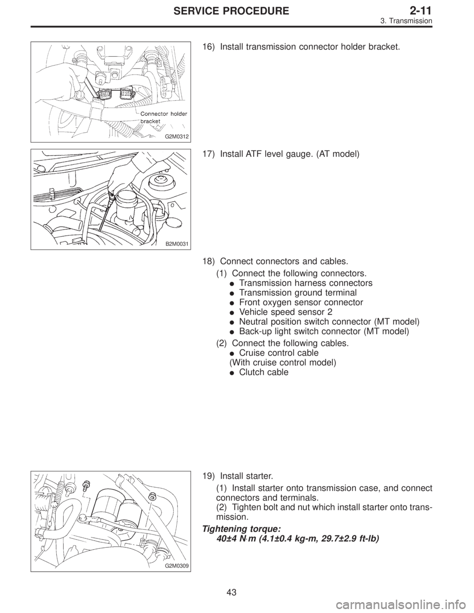
G2M0312
16) Install transmission connector holder bracket.
B2M0031
17) Install ATF level gauge. (AT model)
18) Connect connectors and cables.
(1) Connect the following connectors.
�Transmission harness connectors
�Transmission ground terminal
�Front oxygen sensor connector
�Vehicle speed sensor 2
�Neutral position switch connector (MT model)
�Back-up light switch connector (MT model)
(2) Connect the following cables.
�Cruise control cable
(With cruise control model)
�Clutch cable
G2M0309
19) Install starter.
(1) Install starter onto transmission case, and connect
connectors and terminals.
(2) Tighten bolt and nut which install starter onto trans-
mission.
Tightening torque:
40±4 N⋅m (4.1±0.4 kg-m, 29.7±2.9 ft-lb)
43
2-11SERVICE PROCEDURE
3. Transmission
Page 792 of 2890
 Drive out spring pin�6, and pull out 3-4 fork rod�7and
shifter fork�
8.
NOTE:
When removing rod, keep other rods in neutral. Also, when
pulling out straight pin, remove it toward inside of")
B3M0333B
3) Drive out spring pin�6, and pull out 3-4 fork rod�7and
shifter fork�
8.
NOTE:
When removing rod, keep other rods in neutral. Also, when
pulling out straight pin, remove it toward inside of case so
that it may not hit against case.
4) Drive out straight pin�
9, and pull out 1-2 fork rod�10and
shifter fork�
11.
G3M0602
5) Pull out straight pin�12, and remove idler gear shaft�13,
reverse idler gear�
14and washer�15.
6) Remove outer snap ring�
16, and pull out reverse shifter
rod arm�
17from reverse fork rod�18. Then take out ball,
spring and interlock plunger from rod.
And then remove rod.
NOTE:
When pulling out reverse shifter rod arm, be careful not to
let ball pop out of arm.
7) Remove reverse shifter lever�
19.
G3M0546
8) Remove differential side retainers using ST.
ST 499787000 WRENCH ASSY
G3M0547
9) Remove outer snap ring�20and pull out speedometer
driven gear�
21. Next, remove vehicle speed sensor 2, oil
seal, speedometer shaft�
22and washer.
36
3-1SERVICE PROCEDURE
4. Transmission Case
 Disconnect connector from rear oxygen sensor.
G2M0291
(4) Separate center exhaust pipe from rear exhaust
pipe.
B2M0313
(5) Remove bolt which installs center exhaust pipe on
hunger bracket.")
 Open front hood fully, and support with stay.
2) Disconnect battery ground terminal.
3) Remove air intake duct.
G2M0544
4) Disconnect connectors and cables.
(1) Disconnect the following con")
 Remove transmission connector holder bracket.
G2M0313
10) Set ST.
ST 41099AA020 ENGINE SUPPORT ASSY
NOTE:
Also is available Part No. 927670000.
G2M0299
11) Remove bolt which holds right upp")
 Install hanger bracket on right side of transmission.
(AWD model)
G2M0290
(4) Install front exhaust pipe onto engine.
Tightening torque:
30±5 N⋅m (3.1±0.5 kg-m, 22.4±3.6 ft-lb)
G2M029")