Page 539 of 2890
B2M0335
8. Rear Oxygen Sensor
A: REMOVAL
1. EXCEPT CALIFORNIA 2200 cc MODEL
1) Lift-up the vehicle.
2) Disconnect connector from rear oxygen sensor.
3) Apply SUBARU CRC or its equivalent to threaded por-
tion of rear oxygen sensor, and leave it for one minute or
more.
SUBARU CRC (Part No. 004301003)
B2M0351
4) Remove rear oxygen sensor.
CAUTION:
When removing rear oxygen sensor, do not force rear
oxygen sensor especially when exhaust pipe is cold,
otherwise it will damage exhaust pipe.
B2M0740
2. CALIFORNIA 2200 cc MODEL
1) Disconnect connector from rear oxygen sensor.
2) Lift-up the vehicle.
3) Apply SUBARU CRC or its equivalent to threaded por-
tion of rear oxygen sensor, and leave it for one minute or
more.
SUBARU CRC (Part No. 004301003)
21
2-7SERVICE PROCEDURE
8. Rear Oxygen Sensor
Page 540 of 2890
 Remove rear oxygen sensor.
CAUTION:
When removing rear oxygen sensor, do not force rear
oxygen sensor especially when exhaust pipe is cold,
otherwise it will damage exhaust pipe.
B2M0352A
B")
B2M0741
4) Remove rear oxygen sensor.
CAUTION:
When removing rear oxygen sensor, do not force rear
oxygen sensor especially when exhaust pipe is cold,
otherwise it will damage exhaust pipe.
B2M0352A
B: INSTALLATION
1. EXCEPT CALIFORNIA 2200 cc MODEL
1) Before installing rear oxygen sensor, apply anti-seize
compound only to threaded portion of rear oxygen sensor
to make the next removal easier.
Anti-seize compound:
SS-30 by JET LUBE
CAUTION:
Never apply anti-seize compound to protector of rear
oxygen sensor.
B2M0351
2) Install rear oxygen sensor.
Tightening torque:
21±3 N⋅m (2.1±0.3 kg-m, 15.2±2.2 ft-lb)
3) Connect connector of rear oxygen sensor.
4) Lower the vehicle.
B2M0742A
2. CALIFORNIA 2200 cc MODEL
1) Before installing rear oxygen sensor, apply anti-seize
compound only to threaded portion of rear oxygen sensor
to make the next removal easier.
Anti-seize compound:
SS-30 by JET LUBE
CAUTION:
Never apply anti-seize compound to protector of rear
oxygen sensor.
22
2-7SERVICE PROCEDURE
8. Rear Oxygen Sensor
Page 541 of 2890
B2M0741
2) Install rear oxygen sensor.
Tightening torque:
21±3 N⋅m (2.1±0.3 kg-m, 15.2±2.2 ft-lb)
3) Lower the vehicle.
4) Connect connector to rear oxygen sensor.
23
2-7SERVICE PROCEDURE
8. Rear Oxygen Sensor
Page 542 of 2890
 Disconnect connector from throttle position sensor.
2) Remove throttle position sensor holding screws, and
remove it.
3) Installation")
B2M0162
9. Throttle Position Sensor
A: REMOVAL AND INSTALLATION
1) Disconnect connector from throttle position sensor.
2) Remove throttle position sensor holding screws, and
remove it.
3) Installation is in the reverse order of removal.
Tightening torque:
2.2±0.2 N⋅m (0.22±0.02 kg-m, 1.6±0.1 ft-lb)
CAUTION:
When installing throttle position sensor, adjust to the
specified data.
B2M0163
B: ADJUSTMENT
1) Turn ignition switch to OFF.
2) Loosen throttle position sensor holding screws.
G2M0415
3) When using voltage meter;
(1) Take out ECM.
(2) Turn ignition switch to ON.
(3) Adjust throttle position sensor so that signal voltage
to ECM may be in specification.
Connector & Terminal / Specified voltage
(B84) No. 24 — (B84) No. 25 / 0.45 — 0.55 V
[Fully closed.]
(4) Tighten throttle position sensor holding screws.
G2M0096
4) When using Subaru Select Monitor;
(1) Connect Subaru Select Monitor to the data link con-
nector.
(2) Turn ignition switch to ON and SSM switch to ON.
(3) Select mode “F10”.
(4) Adjust throttle position sensor to specified data.
Condition / Specified data.
Throttle fully closed / 0.50 V
(5) Tighten throttle position sensor holding screws.
24
2-7SERVICE PROCEDURE
9. Throttle Position Sensor
Page 543 of 2890
G2M0416
10. Camshaft Position Sensor
A: REMOVAL AND INSTALLATION
1) Disconnect connector from camshaft position sensor.
G2M0417
2) Remove camshaft position sensor from camshaft sup-
port LH.
3) Installation is in the reverse order of removal.
Tightening torque:
6.4±0.5 N⋅m (0.65±0.05 kg-m, 4.7±0.4 ft-lb)
B2M0355
11. Pressure Sensor (AT model)
A: REMOVAL AND INSTALLATION
1) Disconnect connector from pressure sensor.
2) Disconnect hose from pressure sensor.
B2M0356
3) Remove pressure sensor from bracket.
4) Installation is in the reverse order of removal.
Tightening torque:
6.4±0.5 N⋅m (0.65±0.05 kg-m, 4.7±0.4 ft-lb)
25
2-7SERVICE PROCEDURE
10. Camshaft Position Sensor - 11. Pressure Sensor (AT model)
Page 558 of 2890

�1Clamp
�
2Fuel delivery hose A
�
3Fuel filter bracket
�
4Fuel filter holder
�
5Fuel filter cup
�
6Fuel filter
�
7Evaporation hose
�
8Clip
�
9Fuel delivery hose B
�
10Fuel return hose
�
11Roll over valve
�
12Roll over valve bracket
�
13Evaporation hose H
�
14Evaporation hose I
�
15Evaporation pipe B
�
16Canister hose A
�
17Canister hose B
�
18Canister holder
�
19Canister upper bracket
�
20Cushion rubber
�
21Canister lower bracket
�
22Canister
�
23Fuel pipe ASSY
�
24Fuel filler valve
�
25Fuel filler pipe
�
26Packing�
27Ring A
�
28Ring B
�
29Fuel filler cap
�
30Fuel filler pipe protector
�
31Fuel tank pressure sensor
�
32Fuel tank pressure sensor hose A
�
33Fuel tank pressure sensor bracket
�
34Grommet
�
35Fuel tank pressure sensor hose B
�
36Air ventilator hose A
�
37Air ventilator pipe A
�
38Air ventilator hose B
�
39Air ventilator pipe B
�
40Air ventilator pipe protector
�
41Vent control solenoid valve
�
42Vent control solenoid valve hose
�
43Air filter hose A
�
44Air filter hose B
�
45Air filter
�
46Tapping screw
Tightening torque: N⋅m (kg-m, ft-lb)
T1: 23±7 (2.3±0.7, 17±5.1)
T2: 25±7 (2.5±0.7, 18±5.1)
9
2-8COMPONENT PARTS
2. Fuel Line
Page 578 of 2890
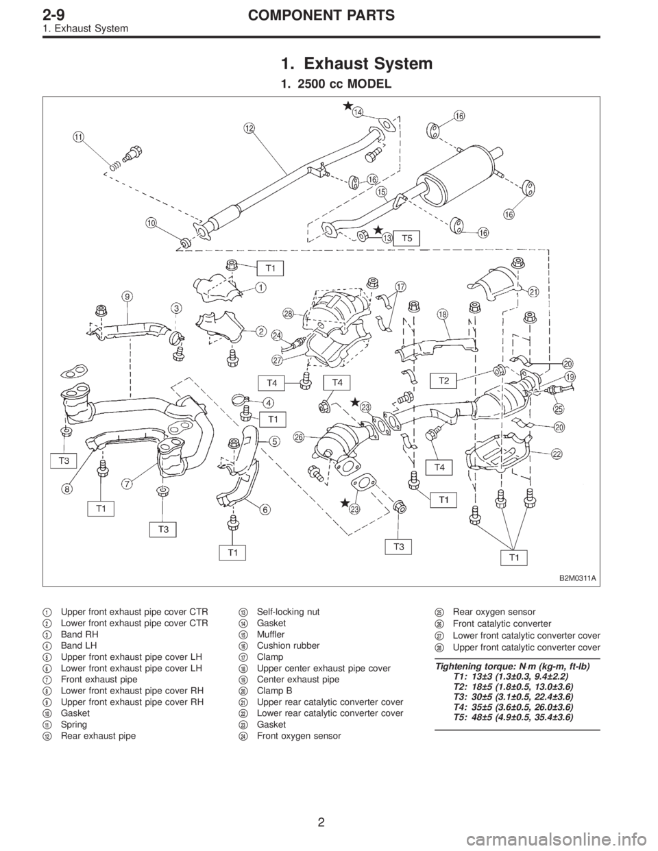
1. Exhaust System
1. 2500 cc MODEL
B2M0311A
�1Upper front exhaust pipe cover CTR
�
2Lower front exhaust pipe cover CTR
�
3Band RH
�
4Band LH
�
5Upper front exhaust pipe cover LH
�
6Lower front exhaust pipe cover LH
�
7Front exhaust pipe
�
8Lower front exhaust pipe cover RH
�
9Upper front exhaust pipe cover RH
�
10Gasket
�
11Spring
�
12Rear exhaust pipe�
13Self-locking nut
�
14Gasket
�
15Muffler
�
16Cushion rubber
�
17Clamp
�
18Upper center exhaust pipe cover
�
19Center exhaust pipe
�
20Clamp B
�
21Upper rear catalytic converter cover
�
22Lower rear catalytic converter cover
�
23Gasket
�
24Front oxygen sensor�
25Rear oxygen sensor
�
26Front catalytic converter
�
27Lower front catalytic converter cover
�
28Upper front catalytic converter cover
Tightening torque: N⋅m (kg-m, ft-lb)
T1: 13±3 (1.3±0.3, 9.4±2.2)
T2: 18±5 (1.8±0.5, 13.0±3.6)
T3: 30±5 (3.1±0.5, 22.4±3.6)
T4: 35±5 (3.6±0.5, 26.0±3.6)
T5: 48±5 (4.9±0.5, 35.4±3.6)
2
2-9COMPONENT PARTS
1. Exhaust System
Page 579 of 2890

2. 2200 cc MODEL
B2M0723A
�1Upper front exhaust pipe cover CTR
�
2Lower front exhaust pipe cover CTR
�
3Band RH
�
4Band LH
�
5Upper front exhaust pipe cover LH
�
6Lower front exhaust pipe cover LH
�
7Front exhaust pipe
�
8Lower front exhaust pipe cover RH
�
9Upper front exhaust pipe cover RH
�
10Gasket
�
11Spring
�
12Rear exhaust pipe
�
13Self-locking nut�
14Gasket
�
15Muffler
�
16Cushion rubber
�
17Clamp
�
18Upper center exhaust pipe cover
�
19Center exhaust pipe
�
20Clamp B
�
21Upper rear catalytic converter cover
�
22Lower rear catalytic converter cover
�
23Gasket
�
24Front oxygen sensor
�
25Rear oxygen sensor (California 2200
cc model)�
26Rear oxygen sensor (Except Califor-
nia 2200 cc model)
�
27Front catalytic converter
�
28Lower front catalytic converter cover
�
29Upper front catalytic converter cover
Tightening torque: N⋅m (kg-m, ft-lb)
T1: 13±3 (1.3±0.3, 9.4±2.2)
T2: 18±5 (1.8±0.5, 13.0±3.6)
T3: 30±5 (3.1±0.5, 22.4±3.6)
T4: 35±5 (3.6±0.5, 26.0±3.6)
T5: 48±5 (4.9±0.5, 35.4±3.6)
3
2-9COMPONENT PARTS
1. Exhaust System
 Lift-up the vehicle.
2) Disconnect connector from rear oxygen sensor.
3) Apply SUBARU CRC or its equivalent to threaded p")
 Install rear oxygen sensor.
Tightening torque:
21±3 N⋅m (2.1±0.3 kg-m, 15.2±2.2 ft-lb)
3) Lower the vehicle.
4) Connect connector to rear oxygen sensor.
23
2-7SERVICE PROCEDURE
8. Rear")
 Disconnect connector from camshaft position sensor.
G2M0417
2) Remove camshaft position sensor from camshaft sup-
port LH.
3) Instal")