Page 304 of 2890

3. Engine Idle Speed
A: MEASUREMENT
1) Before checking idle speed, check the following:
(1) Ensure that air cleaner element is free from
clogging, ignition timing is correct, spark plugs are in
good condition, and that hoses are connected properly.
(2) Ensure that malfunction indicator light (CHECK
ENGINE light) does not illuminate.
2) Warm-up the engine.
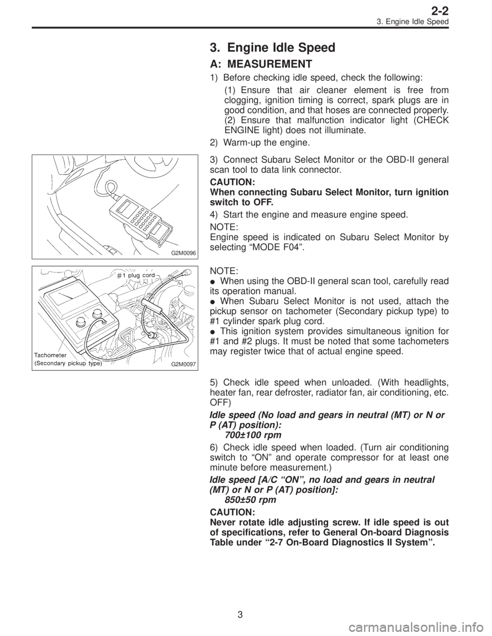
G2M0096
3) Connect Subaru Select Monitor or the OBD-II general
scan tool to data link connector.
CAUTION:
When connecting Subaru Select Monitor, turn ignition
switch to OFF.
4) Start the engine and measure engine speed.
NOTE:
Engine speed is indicated on Subaru Select Monitor by
selecting “MODE F04”.
G2M0097
NOTE:
�When using the OBD-II general scan tool, carefully read
its operation manual.
�When Subaru Select Monitor is not used, attach the
pickup sensor on tachometer (Secondary pickup type) to
#1 cylinder spark plug cord.
�This ignition system provides simultaneous ignition for
#1 and #2 plugs. It must be noted that some tachometers
may register twice that of actual engine speed.
5) Check idle speed when unloaded. (With headlights,
heater fan, rear defroster, radiator fan, air conditioning, etc.
OFF)
Idle speed (No load and gears in neutral (MT) or N or
P (AT) position):
700±100 rpm
6) Check idle speed when loaded. (Turn air conditioning
switch to “ON” and operate compressor for at least one
minute before measurement.)
Idle speed [A/C“ON”, no load and gears in neutral
(MT) or N or P (AT) position]:
850±50 rpm
CAUTION:
Never rotate idle adjusting screw. If idle speed is out
of specifications, refer to General On-board Diagnosis
Table under “2-7 On-Board Diagnostics II System”.
3
2-2
3. Engine Idle Speed
Page 330 of 2890
B2M0108A
3) Measure the extension of rod beyond the body. If it is
not within specifications, replace with a new one.
Rod extension: H
15.4—16.4 mm (0.606—0.646 in)
3. BELT TENSIONER
1) Check mating surfaces of timing belt and contact point
of tension adjuster rod for abnormal wear or scratches.
Replace belt tensioner if faulty.
2) Check spacer and tensioner bushing for wear.
3) Check tensioner for smooth rotation. Replace if noise or
excessive play is noted.
4) Check tensioner for grease leakage.
4. BELT IDLER
1) Check idler for smooth rotation. Replace if noise or
excessive play is noted.
2) Check outer contacting surfaces of idler pulley for
abnormal wear and scratches.
3) Check idler for grease leakage.
5. SPROCKET
1) Check sprocket teeth for abnormal wear and scratches.
2) Make sure there is no free play between sprocket and
key.
3) Check crankshaft sprocket notch for sensor for damage
and contamination of foreign matter.
21
2-3SERVICE PROCEDURE
3. Timing Belt
Page 331 of 2890
C: INSTALLATION
1. SPROCKET
B2M0416B
Tightening torque: N⋅m (kg-m, ft-lb)
T1: 5±1 (0.5±0.1, 3.6±0.7)
T2: 25±2 (2.5±0.2, 18.1±1.4)
T3: 78±5 (8.0±0.5, 57.9±3.6)
G2M0114
1) Install right side belt cover No. 2.
2) Install tensioner bracket.
3) Install left side belt cover No. 2.
4) Install crankshaft sprocket.
5) Install right side camshaft sprocket and left side cam-
shaft sprocket. To lock camshaft use ST.
ST 499207100 CAMSHAFT SPROCKET WRENCH
CAUTION:
Do not confuse left and right side camshaft sprockets
during installation. The left side camshaft sprocket is
identified by a projection used to monitor cam angle
sensor.
22
2-3SERVICE PROCEDURE
3. Timing Belt
Page 342 of 2890
5. Camshaft
A: REMOVAL
1. RELATED PARTS
1) Remove timing belt, camshaft sprockets and related
parts.
2) Remove valve rocker assembly.
2. CAMSHAFT LH
B2M0384A
1) Remove oil level gauge guide attaching bolt.
2) Remove camshaft support LH.
CAUTION:
Do not damage the camshaft position sensor.
3) Remove O-ring.
4) Remove camshaft LH.
5) Remove oil seal.
CAUTION:
�Do not remove oil seal unless necessary.
�Do not scratch journal surface when removing oil
seal.
33
2-3SERVICE PROCEDURE
5. Camshaft
Page 359 of 2890
(7) Further tighten all bolts by 80 to 90°in numerical
sequence.
CAUTION:
Ensure that the total“re-tightening angle”[steps (6)
and (7) above] do not exceed 180°.
3) Install oil level gauge guide attaching bolt (left side
only).
4) Install timing belt, camshaft sprocket and related parts.
2. INTAKE MANIFOLD
CAUTION:
Use dry compressed air to remove foreign particles
before installing each solenoid valve and sensor.
1) Install engine coolant pipe.
2) Install intake manifold.
3) Remove ENGINE STAND (ST).
49
2-3SERVICE PROCEDURE
6. Cylinder Head
Page 408 of 2890
5. SPROCKET
1) Check sprocket teeth for abnormal wear and scratches.
2) Make sure there is no free play between sprocket and
key.
3) Check crankshaft sprocket notch for sensor for damage
and contamination of foreign matter.
C: INSTALLATION
1. SPROCKET
B2M0691B
Tightening torque: N⋅m (kg-m, ft-lb)
T1: 4.9±0.5 (0.5±0.05, 3.6±0.4)
T2: 25±2 (2.5±0.2, 18±1.4)
T3: 78±5 (8.0±0.5, 58±3.6)
B2M0738
1) Install right-hand belt cover No. 2.
20
2-3bSERVICE PROCEDURE
2. Timing Belt
Page 418 of 2890
3. Camshaft
A: REMOVAL
1. RELATED PARTS
Remove timing belt, camshaft sprockets and related parts.
2. CAMSHAFT LH
G2M0743
1) Remove camshaft position sensor.
2) Remove ignition coils.
3) Remove rocker cover and gasket.
G2M0744
4) Loosen intake camshaft cap bolts equally, a little at a
time in the numerical sequence shown in figure.
5) Remove camshaft caps and intake camshaft.
30
2-3bSERVICE PROCEDURE
3. Camshaft
Page 422 of 2890
G2M0755
4) Rocker cover installation
(1) Install gasket on rocker cover.
Install peripheral gasket and ignition coil gasket.
(2) Apply fluid packing to four front open edges of
peripheral gasket.
Fluid packing:
THREE BOND 1215 or equivalent
(3) Install rocker cover on cylinder head. Ensure gas-
ket is properly positioned during installation.
5) Install ignition coil.
6) Install cam angle sensor.
7) Similarly, install parts on right-hand side.
2. RELATED PARTS
Install timing belt, camshaft sprockets and related parts.
34
2-3bSERVICE PROCEDURE
3. Camshaft