Page 1649 of 2890

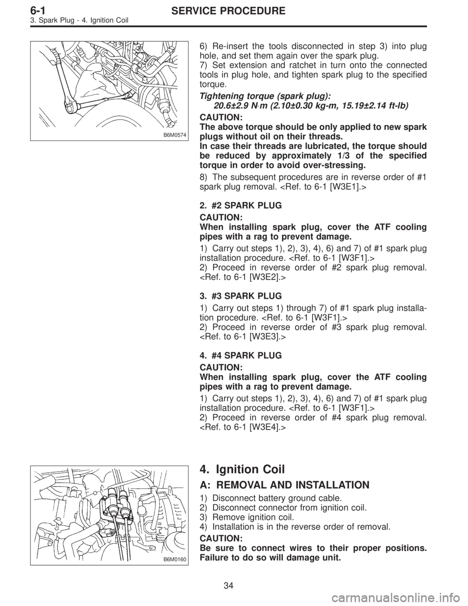
B6M0574
6) Re-insert the tools disconnected in step 3) into plug
hole, and set them again over the spark plug.
7) Set extension and ratchet in turn onto the connected
tools in plug hole, and tighten spark plug to the specified
torque.
Tightening torque (spark plug):
20.6±2.9 N⋅m (2.10±0.30 kg-m, 15.19±2.14 ft-lb)
CAUTION:
The above torque should be only applied to new spark
plugs without oil on their threads.
In case their threads are lubricated, the torque should
be reduced by approximately 1/3 of the specified
torque in order to avoid over-stressing.
8) The subsequent procedures are in reverse order of #1
spark plug removal.
2. #2 SPARK PLUG
CAUTION:
When installing spark plug, cover the ATF cooling
pipes with a rag to prevent damage.
1) Carry out steps 1), 2), 3), 4), 6) and 7) of #1 spark plug
installation procedure.
2) Proceed in reverse order of #2 spark plug removal.
3. #3 SPARK PLUG
1) Carry out steps 1) through 7) of #1 spark plug installa-
tion procedure.
2) Proceed in reverse order of #3 spark plug removal.
4. #4 SPARK PLUG
CAUTION:
When installing spark plug, cover the ATF cooling
pipes with a rag to prevent damage.
1) Carry out steps 1), 2), 3), 4), 6) and 7) of #1 spark plug
installation procedure.
2) Proceed in reverse order of #4 spark plug removal.
B6M0160
4. Ignition Coil
A: REMOVAL AND INSTALLATION
1) Disconnect battery ground cable.
2) Disconnect connector from ignition coil.
3) Remove ignition coil.
4) Installation is in the reverse order of removal.
CAUTION:
Be sure to connect wires to their proper positions.
Failure to do so will damage unit.
34
6-1SERVICE PROCEDURE
3. Spark Plug - 4. Ignition Coil
Page 1659 of 2890

B: INSPECTION
1. BATTERY
1) External parts
Check for the existence of dirt or cracks on the battery
case, top cover, vent plugs, and terminal posts. If
necessary, clean with water and wipe with a dry cloth.
Apply a thin coat of grease on the terminal posts to prevent
corrosion.
2) Electrolyte level
Check the electrolyte level in each cell. If the level is below
MIN LEVEL, bring the level to MAX LEVEL by pouring dis-
tilled water into the battery cell. Do not fill beyond MAX
LEVEL.
WARNING:
�Electrolyte has toxicity; be careful handling the
fluid.
�Avoid contact with skin, eyes or clothing. Especially
at contact with eyes, blush with water for 15 minutes
and get prompt medical attention.
�Batteries produce explosive gasses. Keep sparks,
flame, cigarettes away.
�Ventilate when charging or using in enclosed space.
�For safety, in case an explosion does occur, wear
eye protection or shield your eyes when working near
any battery. Never lean over a battery.
�Do not let battery fluid contact eyes, skin, fabrics, or
paint-work because battery fluid is corrosive acid.
�To lessen the risk of sparks, remove rings, metal
watch-bands, and other metal jewelry. Never allow
metal tools to contact the positive battery terminal and
anything connected to it while you are at the same time
in contact with any other metallic portion of the vehicle
because a short circuit will be caused.
5
6-2SERVICE PROCEDURE
2. Battery
Page 1976 of 2890

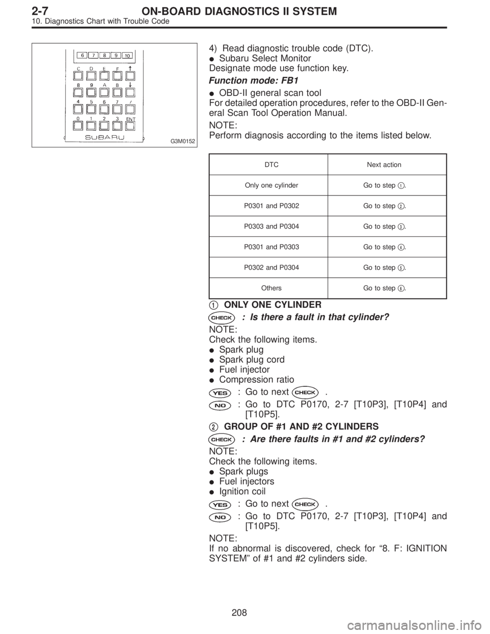
G3M0152
4) Read diagnostic trouble code (DTC).
�Subaru Select Monitor
Designate mode use function key.
Function mode: FB1
�OBD-II general scan tool
For detailed operation procedures, refer to the OBD-II Gen-
eral Scan Tool Operation Manual.
NOTE:
Perform diagnosis according to the items listed below.
DTC Next action
Only one cylinder Go to step�
1.
P0301 and P0302 Go to step�
2.
P0303 and P0304 Go to step�
3.
P0301 and P0303 Go to step�
4.
P0302 and P0304 Go to step�
5.
Others Go to step�
6.
�1ONLY ONE CYLINDER
: Is there a fault in that cylinder?
NOTE:
Check the following items.
�Spark plug
�Spark plug cord
�Fuel injector
�Compression ratio
: Go to next.
: Go to DTC P0170, 2-7 [T10P3], [T10P4] and
[T10P5].
�
2GROUP OF #1 AND #2 CYLINDERS
: Are there faults in #1 and #2 cylinders?
NOTE:
Check the following items.
�Spark plugs
�Fuel injectors
�Ignition coil
: Go to next.
: Go to DTC P0170, 2-7 [T10P3], [T10P4] and
[T10P5].
NOTE:
If no abnormal is discovered, check for“8. F: IGNITION
SYSTEM”of #1 and #2 cylinders side.
208
2-7ON-BOARD DIAGNOSTICS II SYSTEM
10. Diagnostics Chart with Trouble Code
Page 1977 of 2890
�3GROUP OF #3 AND #4 CYLINDERS
: Are there faults in #3 and #4 cylinders?
NOTE:
Check the following items.
�Spark plugs
�Fuel injectors
�Ignition coil
: Go to next.
: Go to DTC P0170, 2-7 [T10P3], [T10P4] and
[T10P5].
NOTE:
If no abnormal is discovered, check for“8. F: IGNITION
SYSTEM”of #3 and #4 cylinders side.
�
4GROUP OF #1 AND #3 CYLINDERS
: Are there faults in #1 and #3 cylinders?
NOTE:
Check the following items.
�Spark plugs
�Fuel injectors
�Skipping timing belt teeth
: Go to next.
: Go to DTC P0170, 2-7 [T10P3], [T10P4] and
[T10P5].
�
5GROUP OF #2 AND #4 CYLINDERS
: Are there faults in #2 and #4 cylinders?
NOTE:
Check the following items.
�Spark plugs
�Fuel injectors
�Skipping timing belt teeth
: Go to next.
: Go to DTC P0170, 2-7 [T10P3], [T10P4] and
[T10P5].
�
6THE CYLINDER AT RANDOM
: Is the engine idle rough?
: Go to next.
: Go to DTC P0170, 2-7 [T10P3], [T10P4] and
[T10P5].
209
2-7ON-BOARD DIAGNOSTICS II SYSTEM
10. Diagnostics Chart with Trouble Code