Page 288 of 2890
4) Installation is in the reverse order of removal.
Tightening torque:
16±1.5 N⋅m (1.6±0.15 kg-m, 11.6±1.1 ft-lb)
B2M0423
5. EGR Valve
A: REMOVAL AND INSTALLATION
1) Disconnect vacuum hose from EGR valve.
2) Remove bolts which install EGR valve onto intake mani-
fold.
3) Installation is in the reverse order of removal.
CAUTION:
Replace gasket with a new one.
Tightening torque:
17.1 — 20.1 N⋅m (1.74 — 2.05 kg-m, 12.6 — 14.8
ft-lb)
B2M0424
6. Back-Pressure Transducer (BPT)
A: REMOVAL AND INSTALLATION
1) Disconnect vacuum hoses from BPT.
2) Remove BPT from bracket.
3) Installation is in the reverse order of removal.
8
2-1SERVICE PROCEDURE
4. Purge Control Solenoid Valve - 6. Back-Pressure Transducer (BPT)
Page 289 of 2890
4) Installation is in the reverse order of removal.
Tightening torque:
16±1.5 N⋅m (1.6±0.15 kg-m, 11.6±1.1 ft-lb)
B2M0423
5. EGR Valve
A: REMOVAL AND INSTALLATION
1) Disconnect vacuum hose from EGR valve.
2) Remove bolts which install EGR valve onto intake mani-
fold.
3) Installation is in the reverse order of removal.
CAUTION:
Replace gasket with a new one.
Tightening torque:
17.1 — 20.1 N⋅m (1.74 — 2.05 kg-m, 12.6 — 14.8
ft-lb)
B2M0424
6. Back-Pressure Transducer (BPT)
A: REMOVAL AND INSTALLATION
1) Disconnect vacuum hoses from BPT.
2) Remove BPT from bracket.
3) Installation is in the reverse order of removal.
8
2-1SERVICE PROCEDURE
4. Purge Control Solenoid Valve - 6. Back-Pressure Transducer (BPT)
Page 290 of 2890
B2M0425A
7. EGR Solenoid Valve
A: REMOVAL AND INSTALLATION
1) Remove bolt which installs EGR solenoid valve onto
intake manifold.
2) Disconnect hoses and connector from EGR solenoid
valve.
NOTE:
This figure shows the rear side of intake manifold.
3) Installation is in the reverse order of removal.
Tightening torque:
19±5 N⋅m (1.9±0.5 kg-m, 13.7±3.6 ft-lb)
G6M0095
8. Fuel Temperature Sensor (2200 cc
AWD Model)
A: REMOVAL
1) Disconnect battery ground cable.
B2M0954A
2) Release fuel pressure.
3) Disconnect fuel delivery hose�
1, return hose�2and jet
pump hose�
3.
B2M0955
4) Remove nuts which install fuel pump assembly onto
fuel tank.
9
2-1SERVICE PROCEDURE
7. EGR Solenoid Valve - 8. Fuel Temperature Sensor (2200 cc AWD Model)
Page 291 of 2890
B2M0425A
7. EGR Solenoid Valve
A: REMOVAL AND INSTALLATION
1) Remove bolt which installs EGR solenoid valve onto
intake manifold.
2) Disconnect hoses and connector from EGR solenoid
valve.
NOTE:
This figure shows the rear side of intake manifold.
3) Installation is in the reverse order of removal.
Tightening torque:
19±5 N⋅m (1.9±0.5 kg-m, 13.7±3.6 ft-lb)
G6M0095
8. Fuel Temperature Sensor (2200 cc
AWD Model)
A: REMOVAL
1) Disconnect battery ground cable.
B2M0954A
2) Release fuel pressure.
3) Disconnect fuel delivery hose�
1, return hose�2and jet
pump hose�
3.
B2M0955
4) Remove nuts which install fuel pump assembly onto
fuel tank.
9
2-1SERVICE PROCEDURE
7. EGR Solenoid Valve - 8. Fuel Temperature Sensor (2200 cc AWD Model)
Page 307 of 2890

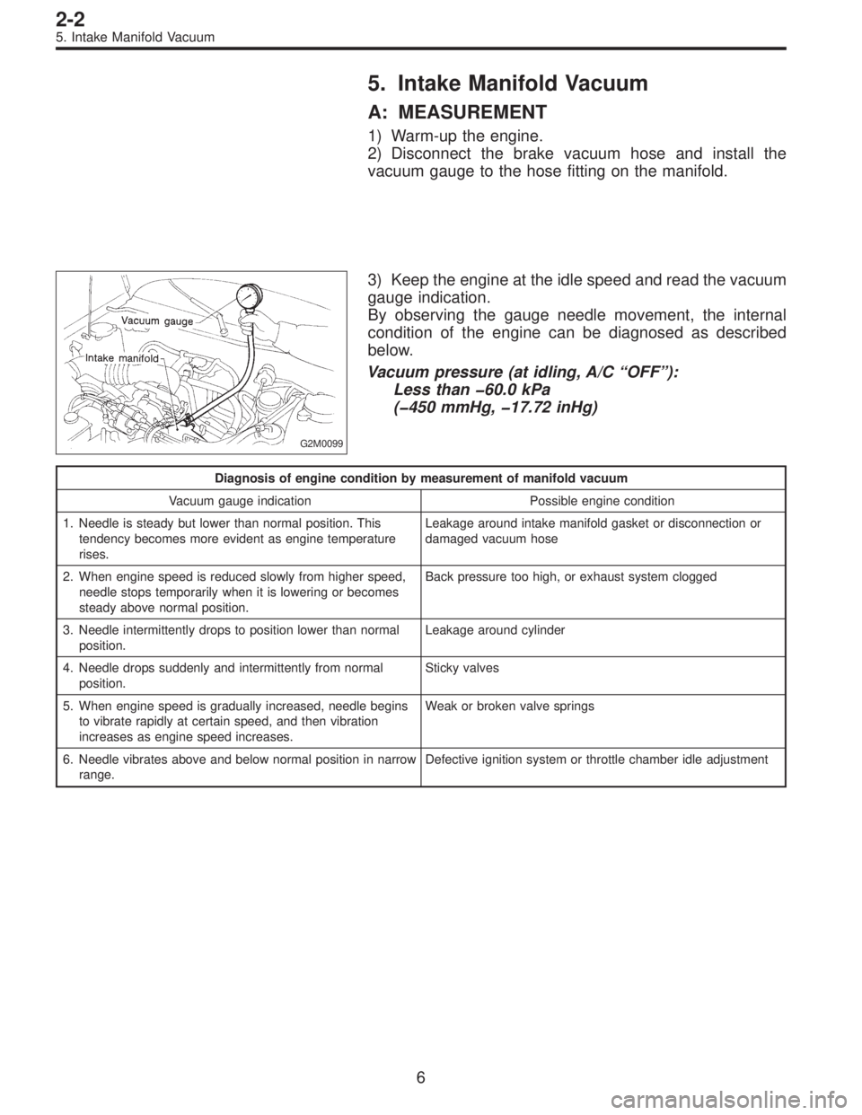
5. Intake Manifold Vacuum
A: MEASUREMENT
1) Warm-up the engine.
2) Disconnect the brake vacuum hose and install the
vacuum gauge to the hose fitting on the manifold.
G2M0099
3) Keep the engine at the idle speed and read the vacuum
gauge indication.
By observing the gauge needle movement, the internal
condition of the engine can be diagnosed as described
below.
Vacuum pressure (at idling, A/C“OFF”):
Less than �60.0 kPa
(�450 mmHg, �17.72 inHg)
Diagnosis of engine condition by measurement of manifold vacuum
Vacuum gauge indication Possible engine condition
1. Needle is steady but lower than normal position. This
tendency becomes more evident as engine temperature
rises.Leakage around intake manifold gasket or disconnection or
damaged vacuum hose
2. When engine speed is reduced slowly from higher speed,
needle stops temporarily when it is lowering or becomes
steady above normal position.Back pressure too high, or exhaust system clogged
3. Needle intermittently drops to position lower than normal
position.Leakage around cylinder
4. Needle drops suddenly and intermittently from normal
position.Sticky valves
5. When engine speed is gradually increased, needle begins
to vibrate rapidly at certain speed, and then vibration
increases as engine speed increases.Weak or broken valve springs
6. Needle vibrates above and below normal position in narrow
range.Defective ignition system or throttle chamber idle adjustment
6
2-2
5. Intake Manifold Vacuum
Page 310 of 2890
1. Engine
A: SPECIFICATIONS
EngineModel2200 cc
TypeHorizontally opposed, liquid cooled, 4-cylinder, 4-stroke
gasoline engine
Valve arrangement Belt driven, single over-head camshaft, 4-valve/cylinder
Bore x Stroke mm (in) 96.9 x 75.0 (3.815 x 2.953)
Displacement cm
3(cu in) 2,212 (135.0)
Compression ratio9.7
Compression pressure
(at 200 — 300 rpm)kPa (kg/cm
2, psi)1,079 — 1,275
(11.0 — 13.0, 156 — 185)
Number of piston rings Pressure ring: 2, Oil ring: 1
Intake valve timingOpening 1° BTDC
Closing 55° ABDC
Exhaust valve timingOpening 48° BBDC
Closing 12° ATDC
Idling speed
[At neutral position on MT, or
“P” or “N” position on AT] rpm700±100 (No load)
850±50 (A/C switch ON)
Firing order1,3,2,4
Ignition timing BTDC/rpm 14°±8°/700 (MT), 20°±8°/700 (AT)
2
2-3SPECIFICATIONS AND SERVICE DATA
1. Engine
Page 311 of 2890

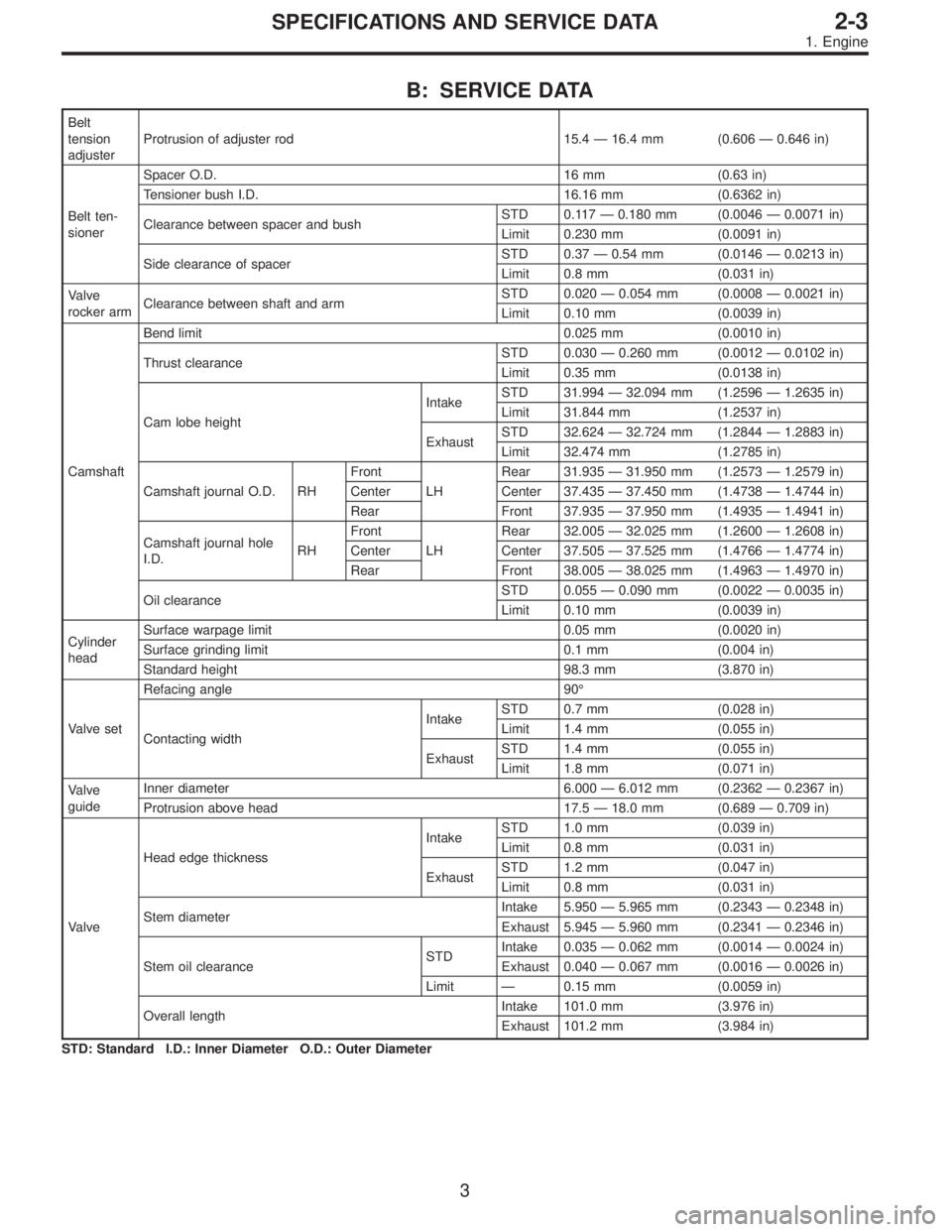
B: SERVICE DATA
Belt
tension
adjusterProtrusion of adjuster rod 15.4—16.4 mm (0.606—0.646 in)
Belt ten-
sionerSpacer O.D. 16 mm (0.63 in)
Tensioner bush I.D. 16.16 mm (0.6362 in)
Clearance between spacer and bushSTD 0.117—0.180 mm (0.0046—0.0071 in)
Limit 0.230 mm (0.0091 in)
Side clearance of spacerSTD 0.37—0.54 mm (0.0146—0.0213 in)
Limit 0.8 mm (0.031 in)
Valve
rocker armClearance between shaft and armSTD 0.020—0.054 mm (0.0008—0.0021 in)
Limit 0.10 mm (0.0039 in)
CamshaftBend limit 0.025 mm (0.0010 in)
Thrust clearanceSTD 0.030—0.260 mm (0.0012—0.0102 in)
Limit 0.35 mm (0.0138 in)
Cam lobe heightIntakeSTD 31.994—32.094 mm (1.2596—1.2635 in)
Limit 31.844 mm (1.2537 in)
ExhaustSTD 32.624—32.724 mm (1.2844—1.2883 in)
Limit 32.474 mm (1.2785 in)
Camshaft journal O.D. RHFront
LHRear 31.935—31.950 mm (1.2573—1.2579 in)
Center Center 37.435—37.450 mm (1.4738—1.4744 in)
Rear Front 37.935—37.950 mm (1.4935—1.4941 in)
Camshaft journal hole
I.D.RHFront
LHRear 32.005—32.025 mm (1.2600—1.2608 in)
Center Center 37.505—37.525 mm (1.4766—1.4774 in)
Rear Front 38.005—38.025 mm (1.4963—1.4970 in)
Oil clearanceSTD 0.055—0.090 mm (0.0022—0.0035 in)
Limit 0.10 mm (0.0039 in)
Cylinder
headSurface warpage limit 0.05 mm (0.0020 in)
Surface grinding limit 0.1 mm (0.004 in)
Standard height 98.3 mm (3.870 in)
Valve setRefacing angle 90°
Contacting widthIntakeSTD 0.7 mm (0.028 in)
Limit 1.4 mm (0.055 in)
ExhaustSTD 1.4 mm (0.055 in)
Limit 1.8 mm (0.071 in)
Valve
guideInner diameter 6.000—6.012 mm (0.2362—0.2367 in)
Protrusion above head 17.5—18.0 mm (0.689—0.709 in)
ValveHead edge thicknessIntakeSTD 1.0 mm (0.039 in)
Limit 0.8 mm (0.031 in)
ExhaustSTD 1.2 mm (0.047 in)
Limit 0.8 mm (0.031 in)
Stem diameterIntake 5.950—5.965 mm (0.2343—0.2348 in)
Exhaust 5.945—5.960 mm (0.2341—0.2346 in)
Stem oil clearanceSTDIntake 0.035—0.062 mm (0.0014—0.0024 in)
Exhaust 0.040—0.067 mm (0.0016—0.0026 in)
Limit—0.15 mm (0.0059 in)
Overall lengthIntake 101.0 mm (3.976 in)
Exhaust 101.2 mm (3.984 in)
STD: Standard I.D.: Inner Diameter O.D.: Outer Diameter
3
2-3SPECIFICATIONS AND SERVICE DATA
1. Engine
Page 315 of 2890
2. Cylinder Head and Camshaft
B2M0103A
�1Rocker cover (RH)
�
2Rocker cover gasket
�
3Camshaft support (RH)
�
4O-ring
�
5Camshaft (RH)
�
6Intake valve guide
�
7Exhaust valve guide
�
8Oil seal
�
9Cylinder head (RH)
�
10Cylinder head gasket
�
11Cylinder head (LH)
�
12Plug
�
13Camshaft (LH)
�
14O-ring
�
15Camshaft support (LH)�
16Oil seal
�
17Oil filler cap
�
18Gasket
�
19Oil filler pipe
�
20O-ring
�
21Rocker cover gasket
�
22Rocker cover (LH)
Tightening torque: N⋅m (kg-m, ft-lb)
T1: Refer to 2-3 [W6E1].
T2: 5±1 (0.5±0.1, 3.6±0.7)
T3: 10 (1.0, 7)
T4: 16 (1.6, 12)
7
2-3COMPONENT PARTS
2. Cylinder Head and Camshaft