Page 414 of 2890

B2M0698A
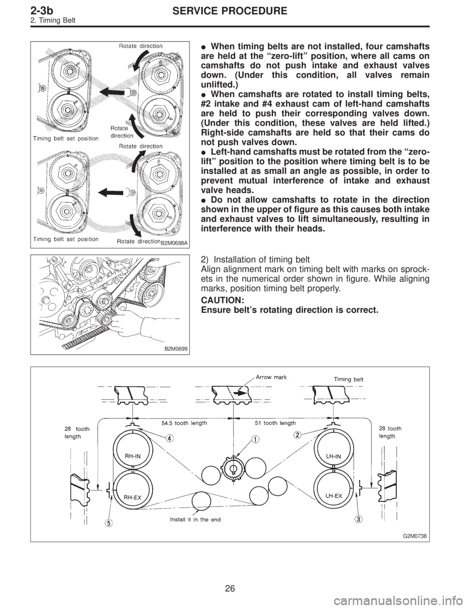
�When timing belts are not installed, four camshafts
are held at the“zero-lift”position, where all cams on
camshafts do not push intake and exhaust valves
down. (Under this condition, all valves remain
unlifted.)
�When camshafts are rotated to install timing belts,
#2 intake and #4 exhaust cam of left-hand camshafts
are held to push their corresponding valves down.
(Under this condition, these valves are held lifted.)
Right-side camshafts are held so that their cams do
not push valves down.
�Left-hand camshafts must be rotated from the“zero-
lift”position to the position where timing belt is to be
installed at as small an angle as possible, in order to
prevent mutual interference of intake and exhaust
valve heads.
�Do not allow camshafts to rotate in the direction
shown in the upper of figure as this causes both intake
and exhaust valves to lift simultaneously, resulting in
interference with their heads.
B2M0699
2) Installation of timing belt
Align alignment mark on timing belt with marks on sprock-
ets in the numerical order shown in figure. While aligning
marks, position timing belt properly.
CAUTION:
Ensure belt’s rotating direction is correct.
G2M0738
26
2-3bSERVICE PROCEDURE
2. Timing Belt
Page 418 of 2890
3. Camshaft
A: REMOVAL
1. RELATED PARTS
Remove timing belt, camshaft sprockets and related parts.
2. CAMSHAFT LH
G2M0743
1) Remove camshaft position sensor.
2) Remove ignition coils.
3) Remove rocker cover and gasket.
G2M0744
4) Loosen intake camshaft cap bolts equally, a little at a
time in the numerical sequence shown in figure.
5) Remove camshaft caps and intake camshaft.
30
2-3bSERVICE PROCEDURE
3. Camshaft
Page 420 of 2890
G2M0138
5) Check cam face condition; remove minor faults by
grinding with oil stone. Measure the cam height H; replace
if the limit has been exceeded.
Standard:
Intake 41.68—41.78 mm (1.6409—1.6449 in)
Exhaust 41.98—42.08 mm (1.6528—1.6567 in)
Limit:
Intake 41.52 mm (1.6346 in)
Exhaust 41.82 mm (1.6465 in)
G2M0748
6) Measure the thrust clearance of camshaft with dial
gauge. If the clearance exceeds the limit, replace caps and
cylinder head as a set. If necessary replace camshaft.
Standard:
0.040—0.080 mm (0.0016—0.0031 in)
Limit:
0.1 mm (0.004 in)
C: INSTALLATION
1. CAMSHAFT
G2M0750
Tightening torque: N⋅m (kg-m, ft-lb)
T1: 10±0.7 (1.0±0.07, 7.2±0.5)
T2: 20±2 (2.0±0.2, 14.5±1.4)
32
2-3bSERVICE PROCEDURE
3. Camshaft
Page 421 of 2890

B2M0764A
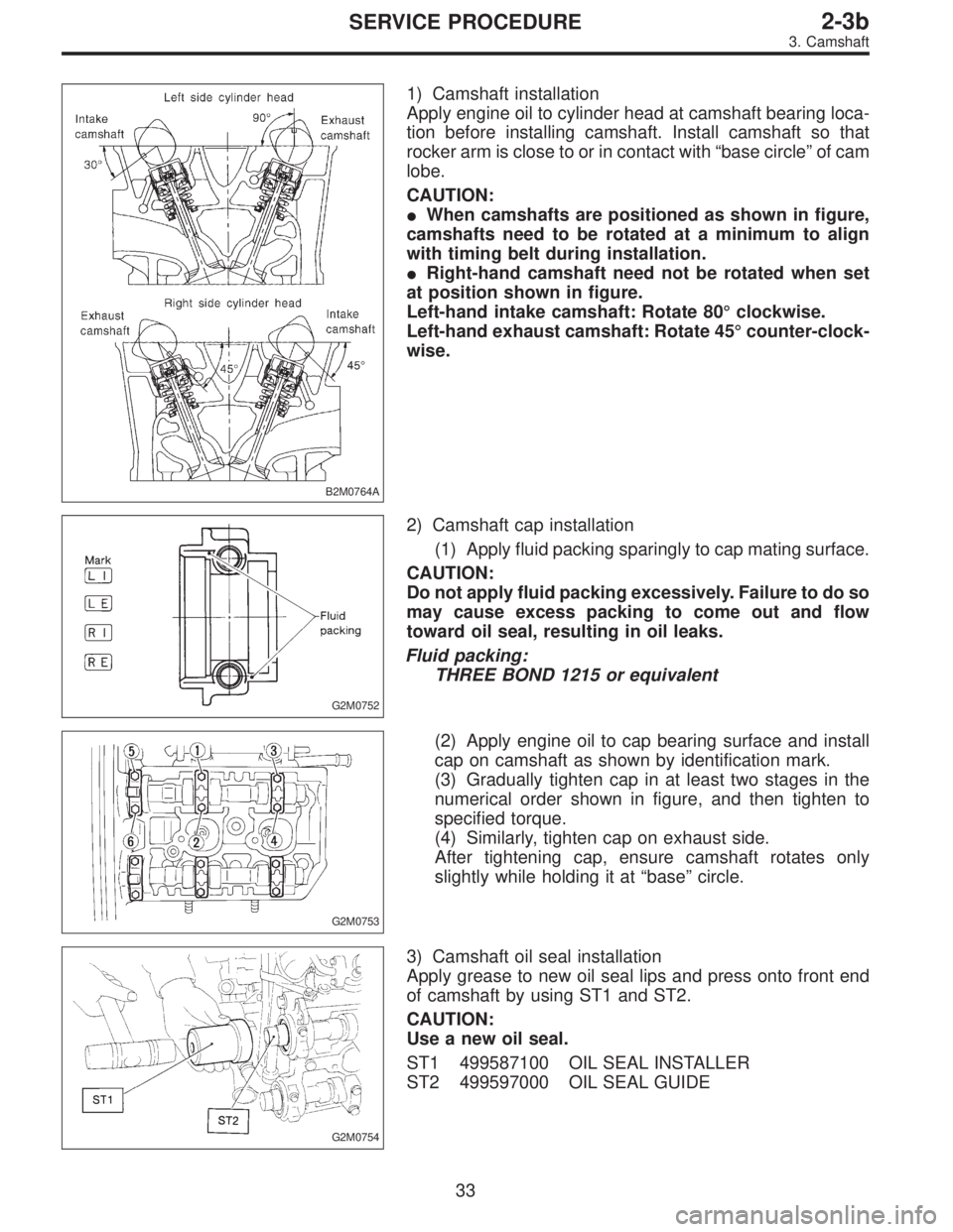
1) Camshaft installation
Apply engine oil to cylinder head at camshaft bearing loca-
tion before installing camshaft. Install camshaft so that
rocker arm is close to or in contact with“base circle”of cam
lobe.
CAUTION:
�When camshafts are positioned as shown in figure,
camshafts need to be rotated at a minimum to align
with timing belt during installation.
�Right-hand camshaft need not be rotated when set
at position shown in figure.
Left-hand intake camshaft: Rotate 80°clockwise.
Left-hand exhaust camshaft: Rotate 45°counter-clock-
wise.
G2M0752
2) Camshaft cap installation
(1) Apply fluid packing sparingly to cap mating surface.
CAUTION:
Do not apply fluid packing excessively. Failure to do so
may cause excess packing to come out and flow
toward oil seal, resulting in oil leaks.
Fluid packing:
THREE BOND 1215 or equivalent
G2M0753
(2) Apply engine oil to cap bearing surface and install
cap on camshaft as shown by identification mark.
(3) Gradually tighten cap in at least two stages in the
numerical order shown in figure, and then tighten to
specified torque.
(4) Similarly, tighten cap on exhaust side.
After tightening cap, ensure camshaft rotates only
slightly while holding it at“base”circle.
G2M0754
3) Camshaft oil seal installation
Apply grease to new oil seal lips and press onto front end
of camshaft by using ST1 and ST2.
CAUTION:
Use a new oil seal.
ST1 499587100 OIL SEAL INSTALLER
ST2 499597000 OIL SEAL GUIDE
33
2-3bSERVICE PROCEDURE
3. Camshaft
Page 423 of 2890
4. Cylinder Head
A: REMOVAL
1. INTAKE MANIFOLD
1) Remove V-belt.
2) Remove generator, air conditioner compressor and
brackets.
3) Remove hoses and tubes from cylinder block.
4) Disconnect each connector and/or remove connector
bracket.
5) Remove coolant filler tank.
6) Remove intake manifold assembly and gasket.
7) Remove water pipe.
8) Remove crank angle sensor, cam angle sensor and
knock sensor.
9) Remove timing belt, camshaft sprockets and related
parts.
10) Remove rocker cover, camshafts and related parts.
2. CYLINDER HEAD
B2M0770A
35
2-3bSERVICE PROCEDURE
4. Cylinder Head
Page 425 of 2890

G2M0759
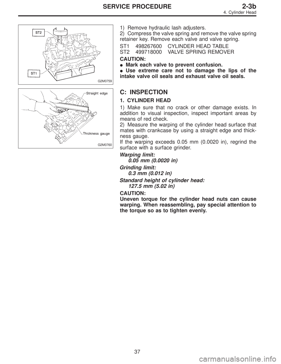
1) Remove hydraulic lash adjusters.
2) Compress the valve spring and remove the valve spring
retainer key. Remove each valve and valve spring.
ST1 498267600 CYLINDER HEAD TABLE
ST2 499718000 VALVE SPRING REMOVER
CAUTION:
�Mark each valve to prevent confusion.
�Use extreme care not to damage the lips of the
intake valve oil seals and exhaust valve oil seals.
G2M0760
C: INSPECTION
1. CYLINDER HEAD
1) Make sure that no crack or other damage exists. In
addition to visual inspection, inspect important areas by
means of red check.
2) Measure the warping of the cylinder head surface that
mates with crankcase by using a straight edge and thick-
ness gauge.
If the warping exceeds 0.05 mm (0.0020 in), regrind the
surface with a surface grinder.
Warping limit:
0.05 mm (0.0020 in)
Grinding limit:
0.3 mm (0.012 in)
Standard height of cylinder head:
127.5 mm (5.02 in)
CAUTION:
Uneven torque for the cylinder head nuts can cause
warping. When reassembling, pay special attention to
the torque so as to tighten evenly.
37
2-3bSERVICE PROCEDURE
4. Cylinder Head
Page 426 of 2890
G2M0761
2. VALVE SEAT
Inspect intake and exhaust valve seats, and correct the
contact surfaces with valve seat cutter if they are defective
or when valve guides are replaced.
Valve seat width: W
Intake
Standard
1.0 mm (0.039 in)
Limit
1.7 mm (0.067 in)
Exhaust
Standard
1.5 mm (0.059 in)
Limit
2.2 mm (0.087 in)
3. VALVE GUIDE
1) Check the clearance between valve guide and stem.
The clearance can be checked by measuring the outside
diameter of valve stem and the inside diameter of valve
guide with outside and inside micrometers respectively.
Clearance between the valve guide and valve stem:
Standard
Intake
0.035—0.062 mm (0.0014—0.0024 in)
Exhaust
0.040—0.067 mm (0.0016—0.0026 in)
Limit
0.15 mm (0.0059 in)
Valve guide inner diameter:
6.000—6.015 mm (0.2362—0.2368 in)
Valve stem outer diameter:
Intake
5.950—5.965 mm (0.2343—0.2348 in)
Exhaust
5.950—5.965 mm (0.2343—0.2348 in)
38
2-3bSERVICE PROCEDURE
4. Cylinder Head
Page 428 of 2890

G2M0153
4. INTAKE AND EXHAUST VALVE
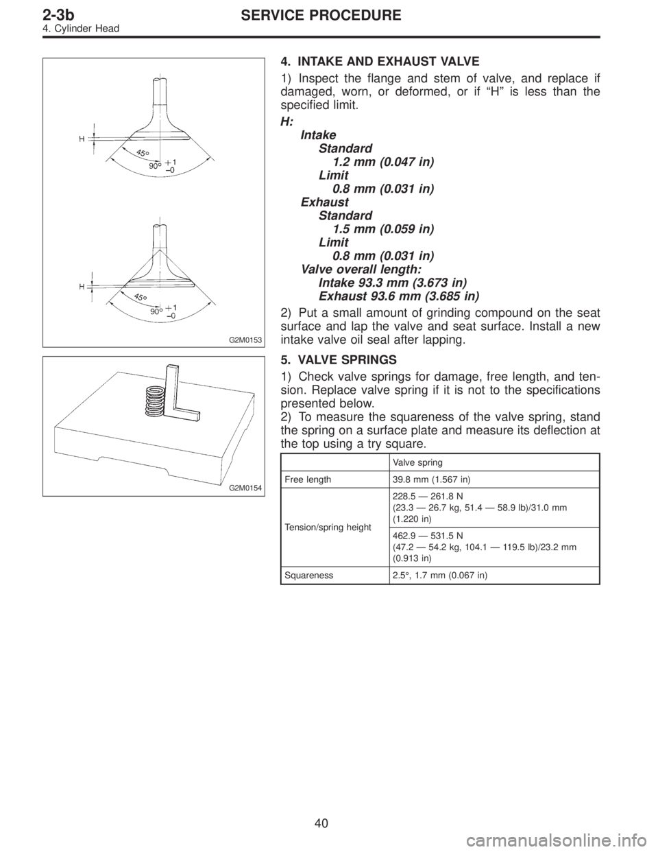
1) Inspect the flange and stem of valve, and replace if
damaged, worn, or deformed, or if“H”is less than the
specified limit.
H:
Intake
Standard
1.2 mm (0.047 in)
Limit
0.8 mm (0.031 in)
Exhaust
Standard
1.5 mm (0.059 in)
Limit
0.8 mm (0.031 in)
Valve overall length:
Intake 93.3 mm (3.673 in)
Exhaust 93.6 mm (3.685 in)
2) Put a small amount of grinding compound on the seat
surface and lap the valve and seat surface. Install a new
intake valve oil seal after lapping.
G2M0154
5. VALVE SPRINGS
1) Check valve springs for damage, free length, and ten-
sion. Replace valve spring if it is not to the specifications
presented below.
2) To measure the squareness of the valve spring, stand
the spring on a surface plate and measure its deflection at
the top using a try square.
Valve spring
Free length 39.8 mm (1.567 in)
Tension/spring height228.5—261.8 N
(23.3—26.7 kg, 51.4—58.9 lb)/31.0 mm
(1.220 in)
462.9—531.5 N
(47.2—54.2 kg, 104.1—119.5 lb)/23.2 mm
(0.913 in)
Squareness 2.5°, 1.7 mm (0.067 in)
40
2-3bSERVICE PROCEDURE
4. Cylinder Head