Page 395 of 2890

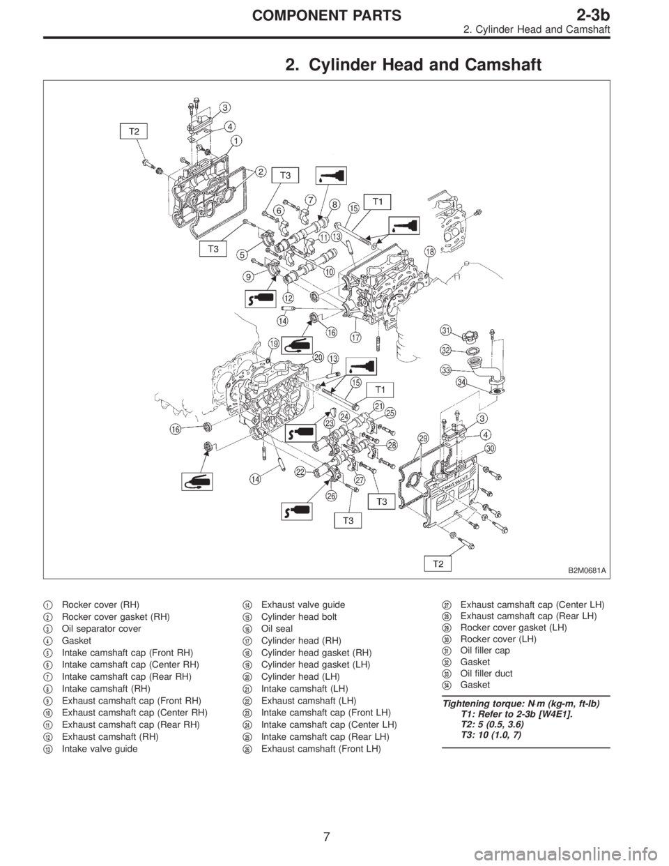
2. Cylinder Head and Camshaft
B2M0681A
�1Rocker cover (RH)
�
2Rocker cover gasket (RH)
�
3Oil separator cover
�
4Gasket
�
5Intake camshaft cap (Front RH)
�
6Intake camshaft cap (Center RH)
�
7Intake camshaft cap (Rear RH)
�
8Intake camshaft (RH)
�
9Exhaust camshaft cap (Front RH)
�
10Exhaust camshaft cap (Center RH)
�
11Exhaust camshaft cap (Rear RH)
�
12Exhaust camshaft (RH)
�
13Intake valve guide�
14Exhaust valve guide
�
15Cylinder head bolt
�
16Oil seal
�
17Cylinder head (RH)
�
18Cylinder head gasket (RH)
�
19Cylinder head gasket (LH)
�
20Cylinder head (LH)
�
21Intake camshaft (LH)
�
22Exhaust camshaft (LH)
�
23Intake camshaft cap (Front LH)
�
24Intake camshaft cap (Center LH)
�
25Intake camshaft cap (Rear LH)
�
26Exhaust camshaft (Front LH)�
27Exhaust camshaft cap (Center LH)
�
28Exhaust camshaft cap (Rear LH)
�
29Rocker cover gasket (LH)
�
30Rocker cover (LH)
�
31Oil filler cap
�
32Gasket
�
33Oil filler duct
�
34Gasket
Tightening torque: N⋅m (kg-m, ft-lb)
T1: Refer to 2-3b [W4E1].
T2: 5 (0.5, 3.6)
T3: 10 (1.0, 7)
7
2-3bCOMPONENT PARTS
2. Cylinder Head and Camshaft
Page 396 of 2890
3. Cylinder Head and Valve Assembly
G2M0706
�1Exhaust valve
�
2Intake valve
�
3Cylinder head
�
4Valve spring seat
�
5Intake valve oil seal
�
6Valve spring
�
7Retainer
�
8Retainer key�
9Hydraulic lash adjuster
�
10Exhaust valve oil seal
Tightening torque: N⋅m (kg-m, ft-lb)
T1: 5 (0.5, 3.6)
T2: 12 (1.2, 9)
8
2-3bCOMPONENT PARTS
3. Cylinder Head and Valve Assembly
Page 402 of 2890
2. TIMING BELT
B2M0685A
G2M0713
B2M0686A
1) If alignment mark and/or arrow mark (which indicates
rotation direction) on timing belt fade away, put new marks
before removing timing belt as follows:
(1) Turn crankshaft using ST, and align alignment
marks on crankshaft sprocket, left-hand intake cam-
shaft sprocket, left-hand exhaust camshaft sprocket,
right-hand intake camshaft sprocket and right hand
exhaust camshaft sprocket with notches of belt cover
and cylinder block.
ST 499987500 CRANKSHAFT SOCKET
14
2-3bSERVICE PROCEDURE
2. Timing Belt
Page 403 of 2890
B2M0687A
(2) Using white paint, put alignment and/or arrow
marks on timing belts in relation to the sprockets.
Z
1: 54.5 tooth length
Z
2: 51 tooth length
Z
3: 28 tooth length
B2M0688
B2M0689
G2M0739
2) Loosen tensioner adjuster mounting bolts.
3) Remove belt idler.
B2M0733
4) Remove timing belt.
5) Remove belt idler No. 2.
CAUTION:
After timing belt has been removed, never rotate intake
and exhaust, camshaft sprocket.
If camshaft sprocket is rotated, the intake and exhaust
valve heads strike together and valve stems are bent.
15
2-3bSERVICE PROCEDURE
2. Timing Belt
Page 405 of 2890
B2M0735
4) Remove belt tension adjuster.
4. SPROCKET
B2M0691A
H2M1294A
1) Remove left-hand intake camshaft sprocket.
2) Remove left-hand exhaust camshaft sprocket.
3) Remove right-hand intake camshaft sprocket.
4) Remove right-hand exhaust camshaft sprocket.
ST 499207300 CAMSHAFT SPROCKET WRENCH
5) Remove crankshaft sprocket.
B2M0736
6) Remove tensioner bracket.
17
2-3bSERVICE PROCEDURE
2. Timing Belt
Page 409 of 2890
B2M0737
2) Install left-hand belt cover No. 2.
B2M0736
3) Install tensioner bracket.
4) Install crankshaft sprocket.
H2M1294A
5) Install right-hand exhaust camshaft sprocket. To lock
camshaft, use ST.
6) Install right-hand intake camshaft sprocket using ST.
7) Install left-hand exhaust camshaft sprocket using ST.
8) Install left-hand intake camshaft sprocket using ST.
ST 499207300 CAMSHAFT SPROCKET WRENCH
21
2-3bSERVICE PROCEDURE
2. Timing Belt
Page 412 of 2890
G2M0728
1) Crankshaft and camshaft sprocket alignment
(1) Align mark on crankshaft sprocket with mark on the
oil pump cover at cylinder block.
B2M0694A
(2) Align single line mark on right-hand exhaust cam-
shaft sprocket with notch on belt cover.
B2M0695A
(3) Align single line mark on right-hand exhaust cam-
shaft sprocket with notch on belt cover.
(Make sure double lines on intake camshaft and
exhaust camshaft sprockets are aligned.)
B2M0696A
(4) Align single line mark on left-hand exhaust cam-
shaft sprocket with notch on belt cover by turning
sprocket counter-clockwise (as viewed from front of
engine).
B2M0697A
(5) Align single line mark on left-hand intake camshaft
sprocket with notch on belt cover by turning sprocket
clockwise (as viewed from front of engine).
Ensure double lines on intake and exhaust camshaft
sprockets are aligned.
24
2-3bSERVICE PROCEDURE
2. Timing Belt
Page 413 of 2890
(6) Ensure camshaft and crankshaft sprockets are
positioned as shown.
G2M0734
G2M0735
CAUTION:
�Intake and exhaust camshafts for this DOHC engine
can be independently rotated with timing belts
removed. As can be seen from the figure, if intake and
exhaust valves are lifted simultaneously, their heads
will interfere with each other, resulting in bent valves.
25
2-3bSERVICE PROCEDURE
2. Timing Belt