Page 91 of 2890
2-7
[T11F0]
ON-BOARD
DIAGNOSTICS
II
SYSTEM
11
.
Diagnostics
Chart
with
Trouble
Code
F
:
DTC
P0115
-
ENGINE
COOLANT
TEMPERATURE
SENSOR
CIRCUIT
MALFUNCTION
(TW)
-
WIRING
DIAGRAM
:
B84
B21
E2E8
ECM
2-Q
FE
884
1
2u34
u
56
u
78
u
171819
20
2122
23242526272829
30
4546
47
484950
5152
53
54555657
71127314757671787980818283
4_Lr
B21
1234
5678
9
1
10
1
11
1
12
~
Engine
coolant
temperature
sensor
E8
12
82M0539
NOTE
:
For
the
diagnostic
ature
sensor
circuit
[T10F0]*2
.
procedure
on
engine
coolant
temper-
malfunction
(DTC
P0115),
refer
to
2-7
80
Page 94 of 2890
ON-BOARD
DIAGNOSTICS
II
SYSTEM
(T11,01
2-7
11
.
Diagnostics
Chart
with
Trouble
Code
Engine
coolant
temperature
sensor
I
:
DTC
P0125
-
INSUFFICIENT
COOLANT
TEMPERATURE
FOR
CLOSED
LOOP
FUEL
CONTROL
(TW
-
CL)
-
WIRING
DIAGRAM
:
B84
B21
E2E8
ECM
B84
B21
ES
1
2u34
U
-1
5
[
6
f
U
78
u
F
5~
55
171819
20
2122
2324
1
25
1
262728
2930
45
1
46
1
47
1
48
1
49
1
50
5152
535455
5657
7172
73
747576
77
787980
8182
83
1234
5678
9
10
1112
12
B2M0539
NOTE
:
For
the
diagnostic
procedure
on
insufficient
coolanttem-
perature
for
closed
loop
fuel
control
(DTC
P0125),
referto
2-7
[T1010]*2
.
83
Page 103 of 2890
![SUBARU LEGACY 1996 Service Repair Manual 2-7
[T11U0]
ON-BOARD
DIAGNOSTICS
II
SYSTEM
11
.
Diagnostics
Chart
with
Trouble
Code
U
:
DTC
P0301
-
CYLINDER
1
MISFIRE
DETECTED
(MIS-1)
-
V
:
DTC
P0302
-
CYLINDER
2
MISFIRE
DETECTED
(MIS-2)
-
SUBARU LEGACY 1996 Service Repair Manual 2-7
[T11U0]
ON-BOARD
DIAGNOSTICS
II
SYSTEM
11
.
Diagnostics
Chart
with
Trouble
Code
U
:
DTC
P0301
-
CYLINDER
1
MISFIRE
DETECTED
(MIS-1)
-
V
:
DTC
P0302
-
CYLINDER
2
MISFIRE
DETECTED
(MIS-2)
-](/manual-img/17/57433/w960_57433-102.png)
2-7
[T11U0]
ON-BOARD
DIAGNOSTICS
II
SYSTEM
11
.
Diagnostics
Chart
with
Trouble
Code
U
:
DTC
P0301
-
CYLINDER
1
MISFIRE
DETECTED
(MIS-1)
-
V
:
DTC
P0302
-
CYLINDER
2
MISFIRE
DETECTED
(MIS-2)
-
W
:
DTC
P0303
-
CYLINDER
3
MISFIRE
DETECTED
(MIS-3)
-
X
:
DTC
P0304
-
CYLINDER
4
MISFIRE
DETECTED
(MIS-4)
-
WIRING
DIAGRAM
:
Crankshaft
Camshaft
Main
rela
y
position
position
Mass
air
o
sensorsensor
flow
sensor
0
O
E10E15
O
B47
ECM
SBF-2
E8
B12
E13
E6
E17
#3
#4
77
Ll
-
t
:A
Engine
Neutral
Throttle
~
E16
coolant
positionposition
temperature
switch
sensor
#1#2
sensor
Fuel
injectors
1
4
10
111
1
14
1
1
1I181920
2122
23
24
25262728
29
3132
33
34353637
3940
4142
4344454647484950
5152
53545556575859
1
60
61
1
62
1
63
1
64
1
65
1
66
1
6L/
1
698
9
0
I
1111721
1741
51761771781191801811827831
8485
861$7
888990
9192
9394951961
I
B22E10E15
O
O
B12E13
B41
Efi
EI7
1234
1
2
5678
~
Et6
5678
_3
1
ill
1
2345
9101112
1
23
56
13141516
1
2
82M0791
NOTE
:
For
the
diagnostic
procedure
on
cylinder
misfire
detected
-
#1
(DTC
P0301),
#2
(DTC
P0302),
#3
(DTC
P0303)
and
#4
(DTC
P0304),
referto
2-7
[T10U0,
T10V0,
T10W0
and
T10X0]*2
.
92
Page 184 of 2890
s-3
[D6013]
6
.
Wiring
Diagram
WIRING
DIAGRAM
Engine
Shield
Boost
Throttle
coolant
point
sensor
position
Knock
temperature
E
.G.R
.
connector
sensor
sensor
sensor
solenoid
B83
H
I
B2
~~
E13
PI
E14
m
I
E8
~I
ElB
..
E2
B21
Ref
.
toAT(
;;
control
system
.
Enginecontro
I
884
module
.
.
..
822
m
mv
E3
m~~;
(Ca
I
i
forn
t
a
mode
l
)
W-
M--
(
9
)
F-F-M-
(
:
9D
Mess
air
Ignitor
flowsensor
(Brown)
E18
E8
(Brown)(Black)
B2
El3
(Brown)
12
123
B3
(Grey)
Bl3
(Gray)
12345123456
Ell
mm
EE
GE
Ignition
coil
E!2
(Gray)
123
82l
(L
i
ght
gray)
1234
5678
9101112
B83
1234
B22
(L
i
ght
gray)
6278
S
1
34
9
101112
3141516
1a
BUR10-02C
14
Page 219 of 2890
![SUBARU LEGACY 1996 Service Repair Manual 2_7
[T10A0]
ON-BOARD
DIAGNOSTICS
11
SYSTEM
10
.
Diagnostics
Chart
with
Trouble
Code
10
.
Diagnostics
Chart
with
Trouble
Code
A
:
DIAGNOSTIC
TROUBLE
CODE
(DTC)
LIST
DTC
No
.
Abbreviation
(Subaru
SUBARU LEGACY 1996 Service Repair Manual 2_7
[T10A0]
ON-BOARD
DIAGNOSTICS
11
SYSTEM
10
.
Diagnostics
Chart
with
Trouble
Code
10
.
Diagnostics
Chart
with
Trouble
Code
A
:
DIAGNOSTIC
TROUBLE
CODE
(DTC)
LIST
DTC
No
.
Abbreviation
(Subaru](/manual-img/17/57433/w960_57433-218.png)
2_7
[T10A0]
ON-BOARD
DIAGNOSTICS
11
SYSTEM
10
.
Diagnostics
Chart
with
Trouble
Code
10
.
Diagnostics
Chart
with
Trouble
Code
A
:
DIAGNOSTIC
TROUBLE
CODE
(DTC)
LIST
DTC
No
.
Abbreviation
(Subaru
select
monitor)Item
Page
P0100
QA
Mass
air
flow
sensor
circuit
malfunction
'1
P0101
QA
-
R
Mass
air
flow
sensor
circuit
range/performance
problem
`1
P0105
P
-
S
Pressure
sensor
circuit
malfunction
*1
P0106
PS
-
R
Pressure
sensor
circuit
range/performance
problem
*1
P0115
TW
Engine
coolant
temperature
sensor
circuit
malfunction
'1
P0120
THV
Throttle
position
sensor
circuit
malfunction
'1
P0121
TH
-
R
Throttle
position
sensor
circuit
range/performance
problem
'1
P0125
TW
-
CL
Insufficient
coolant
temperature
for
closed
loop
fuel
control
'1
P0130
F02
-
V
Front
oxygen
sensor
circuit
malfunction
*1
P0133
F02
-
R
Front
oxygen
sensor
circuit
slowresponse
'1
P0135
F02H
Front
oxygen
sensor
heater
circuit
malfunction
*1
P0136
R02
-
V
Rear
oxygen
sensor
circuit
malfunction
'1
P0139
R02
-
R
Rear
oxygen
sensor
circuit
slowresponse
*1
P0141
R02H
Rear
oxygen
sensor
heater
circuit
malfunction
*1
P0170
FUEL
Fuel
trim
malfunction
'1
P0180
TNKT
Fuel
temperature
sensor
A
circuit
malfunction
10
P0181
TNKT-
FFuel
temperature
sensor
A
circuit
range/performance
problem
16
P0201
INJ1
Fuel
injector
circuit
malfunction
-
#1
P0202
INJ2Fuel
injector
circuit
malfunction
-
#2
"
1
P0203
INJ3Fuel
injector
circuit
malfunction
-
#3
P0204
INJ4Fuel
injector
circuit
malfunction
-
#4
P0301
MIS
-
1
Cylinder
1
misfire
detected
P0302
MIS
-
2Cylinder2
misfire
detected
P0303
MIS
-
3
Cylinder
3
misfire
detected
P0304
MIS
-
4
Cylinder
4
misfire
detected
P0325
KNOCK
Knock
sensor
circuit
malfunction
'1
P0335
CRANK
Crankshaft
position
sensor
circuit
malfunction
'1
P0340
CAM
Camshaft
position
sensor
circuit
malfunction
'1
P0400
EGR
Exhaust
gas
recirculation
flow
malfunction
`1
P0403
EGRSOL
Exhaust
gas
recirculation
circuit
malfunction
'1
P0420
CAT
Catalyst
system
efficiency
below
threshold
'1
P0440
EVAP
Evaporative
emission
control
system
malfunction
18
P0441
CPC
-
F
Evaporative
emission
control
system
incorrect
purge
flow
'1
P0443
CPC
Evaporative
emission
control
system
purge
control
valve
circuit
malfunction
'1
P0446
VCMSOL
Evaporative
emission
control
system
vent
control
malfunction
22
P0450
TNKP
Evaporative
emission
control
system
pressure
sensor
malfunction
28
P0451
TNKP
-
F
Evaporative
emission
control
system
pressure
sensor
range/performance
problem
36
'1
:
.
to
2-7
[T11A0]
.*4>
Page 272 of 2890
6-3
[D6013]
WIRING
DIAGRAM
6
.
Wiring
Diagram
Shield
joint
connector
rE
~
;EB
(
883
E2
B21
Ref
.
toAT
control
system
.
Pressuresensor
....
Englnecontro
I
gg4
module
....
B22
E3
(California
model)
B3
~+~M
B13
Mass
air
Ignitor
flowsensor
(Brown)
E18
E8
(Brown)
(B
I
ack)
B2
E13
(Brown)
12
123
B3
(Grey)
Bl3
(Gray)
12345123456
Ell
(Gray)
123
B21
(L
i
ght
gray)
1234
5678
9
10
ll
l2
Ell
Ignition
coil
883
1234
B22
(L
i
ght
gray)
1
234
S678
9
101112
1
41516
3
fili
BURIO-03C
Eng
i
ne
Throttle
coolant
position
Knock
temperature
E
.
G
.
R
.
sensor
sensor
sensor
solenoid
1
:1
I---I
[--J
[--J
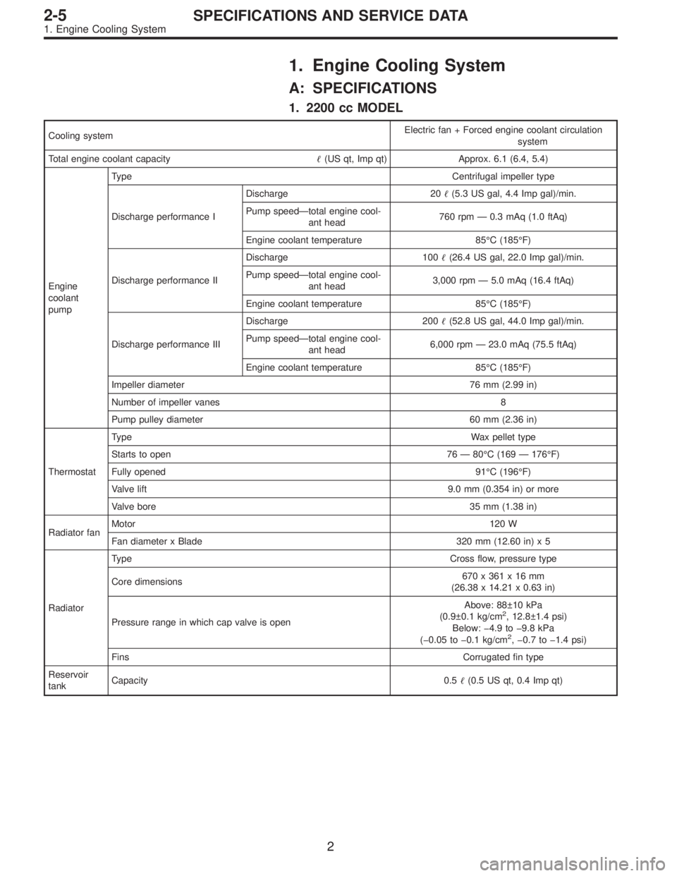
Page 485 of 2890

1. Engine Cooling System
A: SPECIFICATIONS
1. 2200 cc MODEL
Cooling systemElectric fan + Forced engine coolant circulation
system
Total engine coolant capacity�(US qt, Imp qt) Approx. 6.1 (6.4, 5.4)
Engine
coolant
pumpTypeCentrifugal impeller type
Discharge performance IDischarge 20�(5.3 US gal, 4.4 Imp gal)/min.
Pump speed—total engine cool-
ant head760 rpm — 0.3 mAq (1.0 ftAq)
Engine coolant temperature 85°C (185°F)
Discharge performance IIDischarge 100�(26.4 US gal, 22.0 Imp gal)/min.
Pump speed—total engine cool-
ant head3,000 rpm — 5.0 mAq (16.4 ftAq)
Engine coolant temperature 85°C (185°F)
Discharge performance IIIDischarge 200�(52.8 US gal, 44.0 Imp gal)/min.
Pump speed—total engine cool-
ant head6,000 rpm — 23.0 mAq (75.5 ftAq)
Engine coolant temperature 85°C (185°F)
Impeller diameter 76 mm (2.99 in)
Number of impeller vanes 8
Pump pulley diameter 60 mm (2.36 in)
ThermostatTypeWax pellet type
Starts to open 76 — 80°C (169 — 176°F)
Fully opened91°C (196°F)
Valve lift9.0 mm (0.354 in) or more
Valve bore35 mm (1.38 in)
Radiator fanMotor120 W
Fan diameter x Blade 320 mm (12.60 in) x 5
RadiatorTypeCross flow, pressure type
Core dimensions670x361x16mm
(26.38 x 14.21 x 0.63 in)
Pressure range in which cap valve is openAbove: 88±10 kPa
(0.9±0.1 kg/cm
2, 12.8±1.4 psi)
Below: �4.9 to �9.8 kPa
(�0.05 to �0.1 kg/cm
2, �0.7 to �1.4 psi)
FinsCorrugated fin type
Reservoir
tankCapacity 0.5�(0.5 US qt, 0.4 Imp qt)
2
2-5SPECIFICATIONS AND SERVICE DATA
1. Engine Cooling System
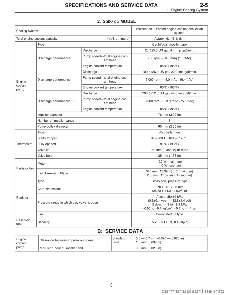
Page 486 of 2890

2. 2500 cc MODEL
Cooling systemElectric fan + Forced engine coolant circulation
system
Total engine coolant capacity�(US qt, Imp qt) Approx. 6.1 (6.4, 5.4)
Engine
coolant
pumpTypeCentrifugal impeller type
Discharge performance IDischarge 20�(5.3 US gal, 4.4 Imp gal)/min.
Pump speed—total engine cool-
ant head760 rpm—0.3 mAq (1.0 ftAq)
Engine coolant temperature 85°C (185°F)
Discharge performance IIDischarge 100�(26.4 US gal, 22.0 Imp gal)/min.
Pump speed—total engine cool-
ant head3,000 rpm—5.0 mAq (16.4 ftAq)
Engine coolant temperature 85°C (185°F)
Discharge performance IIIDischarge 200�(52.8 US gal, 44.0 Imp gal)/min.
Pump speed—total engine cool-
ant head6,000 rpm—23.0 mAq (75.5 ftAq)
Engine coolant temperature 85°C (185°F)
Impeller diameter 76 mm (2.99 in)
Number of impeller vanes 8
Pump pulley diameter 60 mm (2.36 in)
ThermostatTypeWax pellet type
Starts to open 76—80°C (169—176°F)
Fully opened91°C (196°F)
Valve lift9.0 mm (0.354 in) or more
Valve bore35 mm (1.38 in)
Radiator fanMotor120 W (main fan)
140 W (sub fan)
Fan diameter x Blade340 mm (13.39 in) x 5 (main fan)
280 mm (11.02 in) x 4 (sub fan)
RadiatorTypeCross flow, pressure type
Core dimensions670x361x25mm
(26.38 x 14.21 x 0.98 in)
Pressure range in which cap valve is openAbove: 88±10 kPa
(0.9±0.1 kg/cm
2, 12.8±1.4 psi)
Below:�4.9 to�9.8 kPa
(�0.05 to�0.1 kg/cm
2,�0.7 to�1.4 psi)
FinsCorrugated fin type
Reservoir
tankCapacity 0.5�(0.5 US qt, 0.4 Imp qt)
B: SERVICE DATA
Engine
coolant
pumpClearance between impeller and caseStandard
Limit0.5—0.7 mm (0.020—0.028 in)
1.0 mm (0.039 in)
“Thrust”runout of impeller end 0.5 mm (0.020 in)
3
2-5SPECIFICATIONS AND SERVICE DATA
1. Engine Cooling System