Page 516 of 2890
 :
�Engine coolant temperature is below 89°C (192°F).
�A/C switch is turned ON.
�Vehicle speed is over 20 km/h (12 MPH).
Condition (2) :
�Engine coolant")
B: HI MODE OPERATION
CONDITION:
Condition (1) :
�Engine coolant temperature is below 89°C (192°F).
�A/C switch is turned ON.
�Vehicle speed is over 20 km/h (12 MPH).
Condition (2) :
�Engine coolant temperature is above 95°C (203°F).
�A/C switch is turned OFF.
�Vehicle speed is over 20 km/h (12 MPH).
Condition (3) :
�Engine coolant temperature is above 95°C (203°F).
�A/C switch is turned ON.
TROUBLE SYMPTOM:
�Radiator sub fan does not rotate at HI speed under con-
ditions (1), (2) and (3) above.
1. Check operation of sub fan motor LO mode.
OK
�Not OK
Check LO mode operation.
2. Check power supply to sub fan relay-2.
OK
�Not OK
Melted fuse (in A/C relay holder),repair the
shorted part of the circuit,replace fuse.
3. Check sub fan relay-2.
OK
�Not OK
Replace sub fan relay-2.
4. Check harness connector between sub fan
relay-2 and sub fan motor.
OK
�Not OK
Repair or replace wiring harness.
5. Check ground circuit of sub fan motor.
OK
�Not OK
Repair or replace wiring harness.
6. Check sub fan motor.
OK
�Not OK
Replace sub fan motor.
Refer to 2-7 On-Board Diagnostics II System.
�
�
�
�
�
�
33
2-5DIAGNOSTICS
3. Radiator Sub Fan (With A/C model only)
Page 519 of 2890

FUEL INJECTION SYSTEM2-7
Page
C COMPONENT PARTS....................................................................................2
1. Intake Manifold.........................................................................................2
2. Air Intake System.....................................................................................3
3. Air Cleaner ...............................................................................................4
W SERVICE PROCEDURE...............................................................................5
1. Air Cleaner and Air Intake Duct ...............................................................5
2. Mass Air Flow Sensor ..............................................................................6
3. Throttle Body............................................................................................7
4. Intake Manifold.........................................................................................8
5. Engine Coolant Temperature Sensor ....................................................18
6. Crankshaft Position Sensor ...................................................................18
7. Front Oxygen Sensor.............................................................................19
8. Rear Oxygen Sensor .............................................................................21
9. Throttle Position Sensor ........................................................................24
10. Camshaft Position Sensor .....................................................................25
11. Pressure Sensor (AT model)..................................................................25
12. Idle Air Control Solenoid Valve ..............................................................26
13. Pressure Sources Switching Solenoid Valve (AT model) ......................27
14. Fuel Injector ...........................................................................................28
15. Engine Control Module ..........................................................................28
16. Main Relay .............................................................................................30
17. Fuel Pump Relay ...................................................................................31
Page 533 of 2890
G2M0408
4) Connect connector to crankshaft position sensor.
G2M0416
5) Connect connector to camshaft position sensor.
B2M0346
6) Connect connector to knock sensor.
B2M0345A
7) Connect connectors to engine coolant temperature sen-
sor�
1and thermometer�2.
B2M0019
8) Connect engine harness connector to bulkhead har-
ness connectors.
15
2-7SERVICE PROCEDURE
4. Intake Manifold
Page 536 of 2890
B2M0154
18) Install air cleaner element, air cleaner upper cover and
air intake duct.
19) Connect connector to mass air flow sensor.
B2M0154
5. Engine Coolant Temperature Sensor
A: REMOVAL AND INSTALLATION
1) Remove air intake duct.
G2M0407
2) Disconnect connector from engine coolant temperature
sensor.
3) Remove engine coolant temperature sensor.
G2M0407
4) Installation is in the reverse order of removal.
Tightening torque:
25±3 N⋅m (2.5±0.3 kg-m, 18.1±2.2 ft-lb)
G2M0408
6. Crankshaft Position Sensor
A: REMOVAL AND INSTALLATION
1) Remove bolt which install crankshaft position sensor to
cylinder block.
18
2-7SERVICE PROCEDURE
4. Intake Manifold - 6. Crankshaft Position Sensor
Page 596 of 2890

G2M0213
C: INSTALLATION
Installation is in the reverse order of removal.
CAUTION:
�Replace gasket with a new one.
�When installing engine coolant pump, tighten bolts
in two stages in numerical sequence as shown in fig-
ure.
Tightening torque:
10
+4
�0N⋅m (1.0+0.4
�0kg-m, 7.2+2.9
�0ft-lb)
G2M0214
3. Thermostat
A: REMOVAL AND INSTALLATION
1) Drain engine coolant.
Set container under the vehicle, and remove drain cock
from radiator.
2) Disconnect radiator outlet hose from thermostat cover.
3) Remove thermostat cover and gasket, and pull out the
thermostat.
G2M0227
4) Install the thermostat in the intake manifold, and install
the thermostat cover together with a gasket.
CAUTION:
�When reinstalling the thermostat, use a new gasket.
�The thermostat must be installed with the jiggle pin
upward.
�In this time, set the jiggle pin of thermostat for front
side.
G2M0215
B: INSPECTION
Replace the thermostat if the valve does not close com-
pletely at an ambient temperature or if the following test
shows unsatisfactory results.
Immerse the thermostat and a thermometer in water. Raise
water temperature gradually, and measure the temperature
and valve lift when the valve begins to open and when the
valve is fully opened. During the test, agitate the water for
even temperature distribution. The measurement should
be to the specification.
Starts to open:
76.0—80.0°C (169—176°F)
Fully opens:
91°C (196°F)
12
2-5SERVICE PROCEDURE
2. Engine Coolant Pump - 3. Thermostat
Page 606 of 2890

1. Engine Cooling System
Trouble Possible cause Corrective action
Over-heatinga. Insufficient engine coolantReplenish engine coolant, inspect for leakage, and
repair.
b. Loose timing belt Repair or replace timing belt tensioner.
c. Oil on drive belt Replace.
d. Malfunction of thermostat Replace.
e. Malfunction of engine coolant pump Replace.
f. Clogged engine coolant passage Clean.
g. Improper ignition timingInspect and repair ignition control system.
h. Clogged or leaking radiator Clean or repair, or replace.
i. Improper engine oil in engine coolant Replace engine coolant.
j. Air/fuel mixture ratio too leanInspect and repair fuel injection system.
k. Excessive back pressure in exhaust system Clean or replace.
l. Insufficient clearance between piston and cylinder Adjust or replace.
m. Slipping clutch Repair or replace.
n. Dragging brake Adjust.
o. Improper transmission oil Replace.
p. Defective thermostat Replace.
q. Malfunction of electric fanInspect radiator fan relay, engine coolant temperature
sensor or radiator motor and replace there.
Over-coolinga. Atmospheric temperature extremely low Partly cover radiator front area.
b. Defective thermostat Replace.
Engine coolant
leaks.a. Loosened or damaged connecting units on hoses Repair or replace.
b. Leakage from engine coolant pump Replace.
c. Leakage from engine coolant pipe Repair or replace.
d. Leakage around cylinder head gasket Retighten cylinder head bolts or replace gasket.
e. Damaged or cracked cylinder head and crankcase Repair or replace.
f. Damaged or cracked thermostat case Repair or replace.
g. Leakage from radiator Repair or replace.
Noisea. Defective drive belt Replace.
b. Defective radiator fan Replace.
c. Defective engine coolant pump bearing Replace engine coolant pump.
d. Defective engine coolant pump mechanical seal Replace engine coolant pump.
20
2-5DIAGNOSTICS
1. Engine Cooling System
Page 608 of 2890

CONDITION:
�Engine coolant temperature is above 95°C (203°F).
TROUBLE SYMPTOM:
�Radiator main fan does not operate under the above
condition.
1. Check fuse and power")
A: OPERATION (WITHOUT A/C MODEL)
CONDITION:
�Engine coolant temperature is above 95°C (203°F).
TROUBLE SYMPTOM:
�Radiator main fan does not operate under the above
condition.
1. Check fuse and power supply.
OK
�Not OK
Melted fuse,repair the shorted part of the circuit
,replace fuse.
2. Check harness connector between fuse and
relay box, and A/C relay holder.
OK
�Not OK
Repair or replace wiring harness.
3. Check A/C relay holder.
OK
�Not OK
Repair or replace A/C relay holder.
4. Check harness connector between A/C relay
holder and main fan motor.
OK
�Not OK
Repair or replace wiring harness.
5. Check ground circuit of main fan motor.
OK
�Not OK
Repair or replace wiring harness.
6. Check main fan motor.
OK
�Not OK
Replace main fan motor.
Refer to 2-7 On-Board Diagnostics II System.
B2M0427A
1. CHECK FUSE AND POWER SUPPLY.
1) Check fuse No. 13.
2) Turn ignition switch to ACC.
3) Measure voltage between fuse and relay box, and body.
Connector & terminal / Specified voltage:
(F40) No. 3—Body / 10 V, or more
�
�
�
�
�
�
22
2-5DIAGNOSTICS
2. Radiator Main Fan
Page 610 of 2890
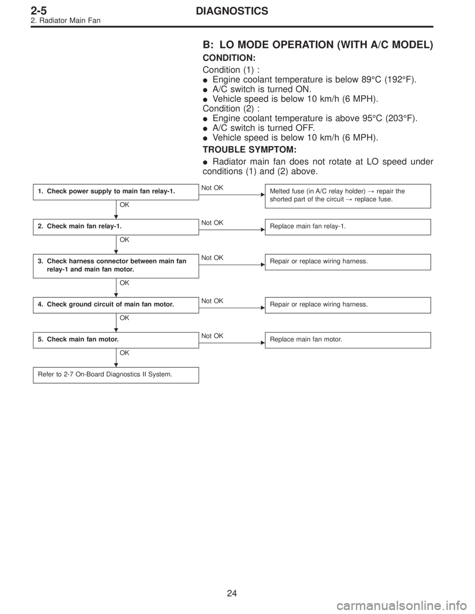
B: LO MODE OPERATION (WITH A/C MODEL)
CONDITION:
Condition (1) :
�Engine coolant temperature is below 89°C (192°F).
�A/C switch is turned ON.
�Vehicle speed is below 10 km/h (6 MPH).
Condition (2) :
�Engine coolant temperature is above 95°C (203°F).
�A/C switch is turned OFF.
�Vehicle speed is below 10 km/h (6 MPH).
TROUBLE SYMPTOM:
�Radiator main fan does not rotate at LO speed under
conditions (1) and (2) above.
1. Check power supply to main fan relay-1.
OK
�Not OK
Melted fuse (in A/C relay holder),repair the
shorted part of the circuit,replace fuse.
2. Check main fan relay-1.
OK
�Not OK
Replace main fan relay-1.
3. Check harness connector between main fan
relay-1 and main fan motor.
OK
�Not OK
Repair or replace wiring harness.
4. Check ground circuit of main fan motor.
OK
�Not OK
Repair or replace wiring harness.
5. Check main fan motor.
OK
�Not OK
Replace main fan motor.
Refer to 2-7 On-Board Diagnostics II System.
�
�
�
�
�
24
2-5DIAGNOSTICS
2. Radiator Main Fan
 Connect connector to crankshaft position sensor.
G2M0416
5) Connect connector to camshaft position sensor.
B2M0346
6) Connect connector to knock sensor.
B2M0345A
7) Connect connectors to en")
 Install air cleaner element, air cleaner upper cover and
air intake duct.
19) Connect connector to mass air flow sensor.
B2M0154
5. Engine Coolant Temperature Sensor
A: REMOVAL AND INSTALL")