Page 1248 of 2890
 Clean back plate and wheel cylinder.
2) Apply grease to portions indicated by arrows in Figure.
Brake grease:
Dow Corning Molykote No. 7439 (Part No.
725191460)
G4M04")
G4M0407
2. BRAKE DRUM AND SHOE
1) Clean back plate and wheel cylinder.
2) Apply grease to portions indicated by arrows in Figure.
Brake grease:
Dow Corning Molykote No. 7439 (Part No.
725191460)
G4M0408
3) Apply grease to adjusting screw and both ends of
adjuster.
Brake grease:
Dow Corning Molykote No. 7439 (Part No.
725191460)
4) Connect upper shoe return spring to shoes.
G4M0409
5) While positioning shoes (one at a time) in groove on
wheel cylinder, secure shoes.
6) Connect lower shoe return spring.
7) Fix shoes by connecting hold-down cup to hold-down
pin.
G4M0400
3. BRAKE ASSEMBLY
1) Install brake assembly on housing, and tighten bolts to
install back plate.
Tightening torque:
52±6 N⋅m (5.3±0.6 kg-m, 38.3±4.3 ft-lb)
2) Install hub.
3) Connect brake pipe, and tighten brake pipe flange nut.
Tightening torque:
15
+3
�2N⋅m (1.5+0.3
�0.2kg-m, 10.8+2.2
�1.4ft-lb)
4) Set the outside diameter of brake shoes less than 0.5
to 0.8 mm (0.020 to 0.031 in) in comparison with the inside
diameter of brake drum.
5) Install brake drum.
6) After installing brake assembly, bleed air from brake
line.
43
4-4SERVICE PROCEDURE
3. Rear Drum Brake
Page 1262 of 2890
 Separate brake pipe from brake hose.
(Always use flare nut wrench and be careful not to deform
flare nut.)
2) Pull out clamp to remove brake hose.
3) Remove clamp a")
G4M0426
7. Brake Hose
A: REMOVAL
1) Separate brake pipe from brake hose.
(Always use flare nut wrench and be careful not to deform
flare nut.)
2) Pull out clamp to remove brake hose.
3) Remove clamp at strut and union bolt.
G4M0427
B: INSTALLATION
1. FRONT BRAKE HOSE
1) Route end of brake hose (on caliper side) through hole
in brake hose bracket at strut location.
2) Tighten end of brake hose at caliper using a union bolt.
Tightening torque (Union bolt):
18±3 N⋅m (1.8±0.3 kg-m, 13.0±2.2 ft-lb)
3) Secure middle fitting of brake hose to bracket at strut
location using a clamp.
4) Position disc in straight-forward direction and route
brake hose through hole in bracket on wheel apron side.
CAUTION:
Be sure brake hose is not twisted.
5) Temporarily tighten flare nut to connect brake pipe and
hose.
6) Fix brake hose with clamp at wheel apron bracket.
7) While holding hexagonal part of brake hose fitting with
a wrench, tighten flare nut to the specified torque.
Tightening torque (Brake pipe flare nut):
15
+3
�2N⋅m (1.5+0.3
�0.2kg-m, 10.8+2.2
�1.4ft-lb)
8) Bleed air from the brake system.
2. REAR BRAKE HOSE
1) Pass brake hose through the hole of bracket, and lightly
tighten flare nut to connect brake pipe.
2) Insert clamp upward to fix brake hose.
3) Perform the same procedures as before mentioned in
steps 7) and 8).
56
4-4SERVICE PROCEDURE
7. Brake Hose
Page 1267 of 2890
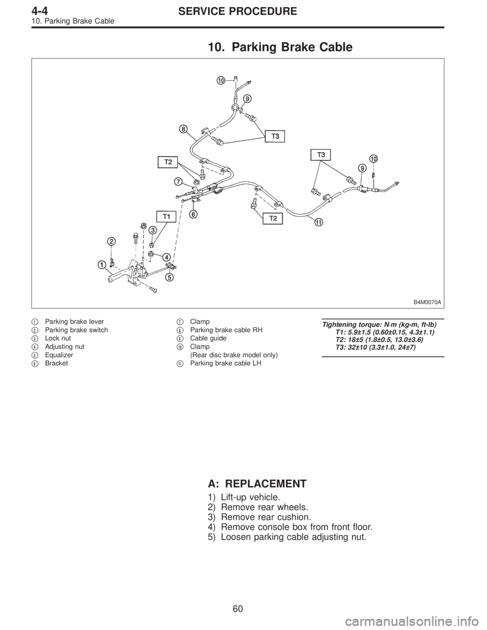
10. Parking Brake Cable
B4M0070A
�1Parking brake lever
�
2Parking brake switch
�
3Lock nut
�
4Adjusting nut
�
5Equalizer
�
6Bracket�
7Clamp
�
8Parking brake cable RH
�
9Cable guide
�
10Clamp
(Rear disc brake model only)
�
11Parking brake cable LH
Tightening torque: N⋅m (kg-m, ft-lb)
T1: 5.9±1.5 (0.60±0.15, 4.3±1.1)
T2: 18±5 (1.8±0.5, 13.0±3.6)
T3: 32±10 (3.3±1.0, 24±7)
A: REPLACEMENT
1) Lift-up vehicle.
2) Remove rear wheels.
3) Remove rear cushion.
4) Remove console box from front floor.
5) Loosen parking cable adjusting nut.
60
4-4SERVICE PROCEDURE
10. Parking Brake Cable
Page 1269 of 2890

A: GENERAL RULES FOR EFFECTIVE
BLEEDING
1) Start with the brakes (wheels) connecting to the sec-
ondary chamber of the master cylinder.
2) The time interval betwee")
11. Air Bleeding (Without TCS model)
A: GENERAL RULES FOR EFFECTIVE
BLEEDING
1) Start with the brakes (wheels) connecting to the sec-
ondary chamber of the master cylinder.
2) The time interval between two brake pedal operations
(from the time when the pedal is released to the time when
it is depressed another time) shall be approximately 3 sec-
onds.
3) The air bleeder on each brake shall be released for 1
to 2 seconds.
B: BLEEDING PROCEDURE
CAUTION:
�The FMVSS No. 116, fresh DOT3 or 4 brake fluid
must be used.
�Cover bleeder with waste cloth, when loosening it,
to prevent brake fluid from being splashed over sur-
rounding parts.
�Avoid mixing different brands of brake fluid to pre-
vent degrading the quality of the fluid.
�Be careful not to allow dirt or dust to get into the
reservoir tank.
NOTE:
�During bleeding operation, keep the brake reserve tank
filled with brake fluid to eliminate entry of air.
�Brake pedal operating must be very slow.
�For convenience and safety, it is advisable to have two
man working.
G4M0434
G4M0435
1) Make sure that there is no leak from joints and connec-
tions of the brake system.
2) Fit one end of vinyl tube into the air bleeder and put the
other end into a brake fluid container.
3) Slowly depress the brake pedal and keep it depressed.
Then, open the air bleeder to discharge air together with
the fluid.
Release air bleeder for 1 to 2 seconds.
Next, with the bleeder closed, slowly release the brake
pedal.
Repeat these steps until there are no more air bubbles in
the vinyl tube.
Allow 3 to 4 seconds between two brake pedal operations.
CAUTION:
Cover bleeder with waste cloth, when loosening it, to
prevent brake fluid from being splashed over sur-
rounding parts.
NOTE:
Brake pedal operating must be very slow.
4) Tighten air bleeder securely when no air bubbles are
visible.
62
4-4SERVICE PROCEDURE
11. Air Bleeding (Without TCS model)
Page 1270 of 2890

5) Perform these steps for the brakes connecting to the
secondary chamber of master cylinder, first, and then for
the ones con")
Air bleeder tightening torque:
8±1 N⋅m (0.8±0.1 kg-m, 5.8±0.7 ft-lb)
5) Perform these steps for the brakes connecting to the
secondary chamber of master cylinder, first, and then for
the ones connecting to primary chamber. With all proce-
dures completed, fully depress the brake pedal and keep
it in that position for approximately 20 seconds to make
sure that there is no leak evident in the entire system.
G4M0436
6) Perform sequence control. (With ABS model)
4-4 [W15C1].>
7) Check the pedal stroke.
While the engine is idling, depress the brake pedal with a
490 N (50 kg, 110 lb) load and measure the distance
between the brake pedal and steering wheel. With the
brake pedal released, measure the distance between the
pedal and steering wheel again. The difference between
the two measurements must be more than specified.
Specified pedal stroke:
Without ABS
90 mm (3.54 in)
With ABS
95 mm (3.74 in)
When depressing brake pedal with a 490 N (50 kg,
110 lb) load.
(1) Models without ABS
If the distance is more than specifications, there is a
possibility that air is in the brake line. Bleed air from the
brake line.
(2) Models with ABS
If the distance is more than specifications, there is a
possibility air is in the inside of the hydraulic unit.
Therefore, air must be bled from the inside of the
hydraulic unit to the brake pipes in accordance with the
bleeding sequence control.
8) Add brake fluid to the required level (MAX. level) of
reserve tank.
9) As a final step, test run the vehicle at low speed and
apply brakes relatively hard 2 to 3 times to ensure that
brakes provide normal braking action on all four wheels
without dragging and uneven braking.
63
4-4SERVICE PROCEDURE
11. Air Bleeding (Without TCS model)
Page 1271 of 2890

12. Brake Fluid Replacement
NOTE:
To always maintain the brake fluid characteristics, replace
the brake fluid according to maintenance schedule or ear-
lier than that when used in severe condition.
A: REPLACEMENT
CAUTION:
�The FMVSS No. 116, fresh DOT3 or 4 brake fluid
must be used.
�Cover bleeder with waste cloth, when loosening it,
to prevent brake fluid from being splashed over sur-
rounding parts.
�Avoid mixing different brands of brake fluid to pre-
vent degrading the quality of the fluid.
�Be careful not to allow dirt or dust to get into the
reservoir tank.
NOTE:
�During bleeding operation, keep the brake reserve tank
filled with brake fluid to eliminate entry of air.
�Brake pedal operating must be very slow.
�For convenience and safety, it is advisable to have two
man working.
�The amount of brake fluid required is approximately 500
m�(16.9 US fl oz, 17.6 Imp fl oz) for total brake system.
1) Either jack-up vehicle and place a safety stand under it,
or lift-up vehicle.
2) Remove both front and rear wheels.
3) Draw out the brake fluid from reserve tank with syringe.
4) Refill reservoir tank with recommended brake fluid.
Recommended brake fluid:
FMVSS No. 116, fresh DOT3 or 4 brake fluid
64
4-4SERVICE PROCEDURE
12. Brake Fluid Replacement
Page 1272 of 2890
 Install one end of a vinyl tube onto the air bleeder of and
insert the other end of the tube into a container to collect
the brake fluid.
6) Instruct your co-worker to depre")
G4M0434
G4M0438
G4M0435
5) Install one end of a vinyl tube onto the air bleeder of and
insert the other end of the tube into a container to collect
the brake fluid.
6) Instruct your co-worker to depress the brake pedal
slowly two or three times and then hold it depressed.
7) Loosen bleeder screw approximately 1/4 turn until a
small amount of brake fluid drains into container, and then
quickly tighten screw.
8) Repeat steps 6) and 7) above until there are no air
bubbles in drained brake fluid and new fluid flows through
vinyl tube.
CAUTION:
Add brake fluid as necessary while performing the air
bleed operation, in order to prevent the tank from run-
ning short of brake fluid.
9) After completing the bleeding operation, hold brake
pedal depressed and tighten screw and install bleeder cap.
Tightening torque (Bleeder screw):
8±1 N⋅m (0.8±0.1 kg-m, 5.8±0.7 ft-lb)
10) Bleed air from each wheel cylinder using the same
procedures as described in steps 6) through 7) above.
11) Depress brake pedal with a force of approximately 294
N (30 kg, 66 lb) and hold it there for approximately 20 sec-
onds. At this time check pedal to see if it shows any
unusual movement.
Visually inspect bleeder screws and brake pipe joints to
make sure that there is no fluid leakage.
12) Install wheels, and drive vehicle for a short distance
between 2 to 3 km (1 to 2 miles) to make sure that brakes
are operating properly.
65
4-4SERVICE PROCEDURE
12. Brake Fluid Replacement
Page 1273 of 2890
 Install the oil pressure gauges to measure the master
cylinder fluid pressure (front wheel brake fluid pressure)
and rear wheel cylinde")
G4M0440
13. Proportioning Valve
G4M0668
G4M0915
A: INSPECTION
1) Install the oil pressure gauges to measure the master
cylinder fluid pressure (front wheel brake fluid pressure)
and rear wheel cylinder fluid pressure.
2) Bleed air from the oil pressure gauges.
3) Check the master cylinder fluid pressure and rear wheel
cylinder fluid pressure.
The standard values are shown in Figure.
4) For the oil pressure in case of split point, refer to A:
SPECIFICATIONS 4-4 [S0A0].
B: REMOVAL
1) Remove brake pipe from proportioning valve at four
places.
2) Remove proportioning valve from its bracket.
CAUTION:
Do not disassemble or adjust the proportioning valve.
(The proportioning valve must be replaced as an
assembly.)
C: INSTALLATION
1) Install proportioning valve to bracket.
2) Connect brake pipes correctly to proportioning valve.
3) Bleed air, then check each joint of brake pipe for oil
leaks.
Tightening torque:
Proportioning valve to brake pipe flare nut:
15
+3
�2N⋅m (1.5+0.3
�0.2kg-m, 10.8+2.2
�1.4ft-lb)
Proportioning valve to bracket:
18±5 N⋅m (1.8±0.5 kg-m, 13.0±3.6 ft-lb)
66
4-4SERVICE PROCEDURE
13. Proportioning Valve