Page 1148 of 2890
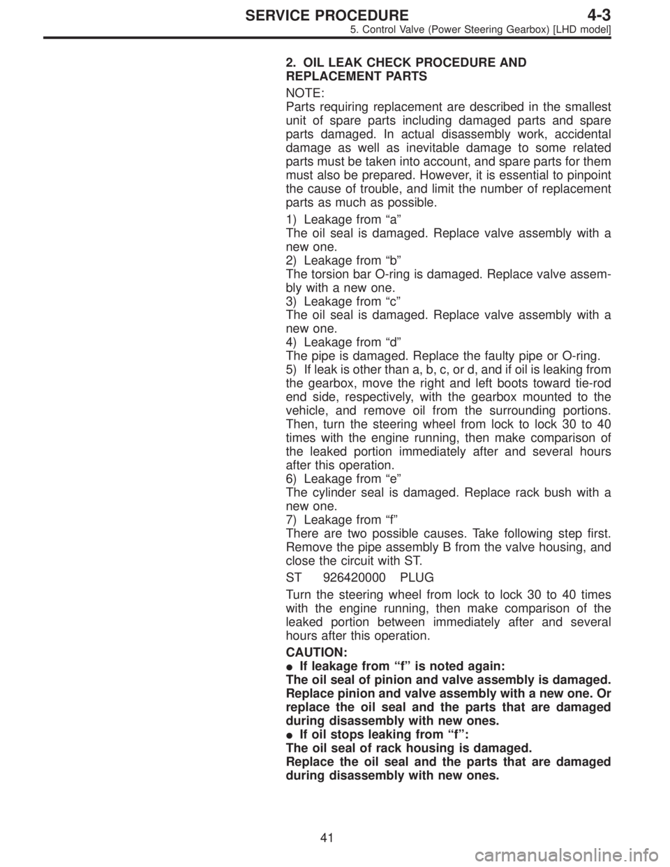
2. OIL LEAK CHECK PROCEDURE AND
REPLACEMENT PARTS
NOTE:
Parts requiring replacement are described in the smallest
unit of spare parts including damaged parts and spare
parts damaged. In actual disassembly work, accidental
damage as well as inevitable damage to some related
parts must be taken into account, and spare parts for them
must also be prepared. However, it is essential to pinpoint
the cause of trouble, and limit the number of replacement
parts as much as possible.
1) Leakage from“a”
The oil seal is damaged. Replace valve assembly with a
new one.
2) Leakage from“b”
The torsion bar O-ring is damaged. Replace valve assem-
bly with a new one.
3) Leakage from“c”
The oil seal is damaged. Replace valve assembly with a
new one.
4) Leakage from“d”
The pipe is damaged. Replace the faulty pipe or O-ring.
5) If leak is other than a, b, c, or d, and if oil is leaking from
the gearbox, move the right and left boots toward tie-rod
end side, respectively, with the gearbox mounted to the
vehicle, and remove oil from the surrounding portions.
Then, turn the steering wheel from lock to lock 30 to 40
times with the engine running, then make comparison of
the leaked portion immediately after and several hours
after this operation.
6) Leakage from“e”
The cylinder seal is damaged. Replace rack bush with a
new one.
7) Leakage from“f”
There are two possible causes. Take following step first.
Remove the pipe assembly B from the valve housing, and
close the circuit with ST.
ST 926420000 PLUG
Turn the steering wheel from lock to lock 30 to 40 times
with the engine running, then make comparison of the
leaked portion between immediately after and several
hours after this operation.
CAUTION:
�If leakage from“f”is noted again:
The oil seal of pinion and valve assembly is damaged.
Replace pinion and valve assembly with a new one. Or
replace the oil seal and the parts that are damaged
during disassembly with new ones.
�If oil stops leaking from“f”:
The oil seal of rack housing is damaged.
Replace the oil seal and the parts that are damaged
during disassembly with new ones.
41
4-3SERVICE PROCEDURE
5. Control Valve (Power Steering Gearbox) [LHD model]
Page 1156 of 2890
![SUBARU LEGACY 1996 Service Repair Manual 6. Control Valve (Power Steering
Gearbox) [RHD model]
NOTE:
This section focuses on the disassembly and reassembly
of control valve. For the inspection and adjustment and the
service procedures for as SUBARU LEGACY 1996 Service Repair Manual 6. Control Valve (Power Steering
Gearbox) [RHD model]
NOTE:
This section focuses on the disassembly and reassembly
of control valve. For the inspection and adjustment and the
service procedures for as](/manual-img/17/57433/w960_57433-1155.png)
6. Control Valve (Power Steering
Gearbox) [RHD model]
NOTE:
This section focuses on the disassembly and reassembly
of control valve. For the inspection and adjustment and the
service procedures for associated parts, refer to“Steering
Gearbox”.
B4M0668A
A: CHECKING OIL LEAKING POINTS
1. OIL LEAKING POINTS
1) If leak point is other than a, b, c, or d, perform check
step 5) in 4-3 [W6A2] before dismounting gearbox from
vehicle. If gearbox is dismounted without confirming where
the leak is, it must be mounted again to locate the leak
point.
2) Even if the location of the leak can be easily found by
observing the leaking condition, it is necessary to thor-
oughly remove the oil from the suspected portion and turn
the steering wheel from lock to lock about 30 to 40 times
with engine running, then make comparison of the sus-
pected portion between immediately after and several
hours after this operation.
3) Before starting oil leak repair work, be sure to clean the
gearbox, hoses, pipes, and surrounding parts. After com-
pleting repair work, clean these areas again.
49
4-3SERVICE PROCEDURE
6. Control Valve (Power Steering Gearbox) [RHD model]
Page 1157 of 2890
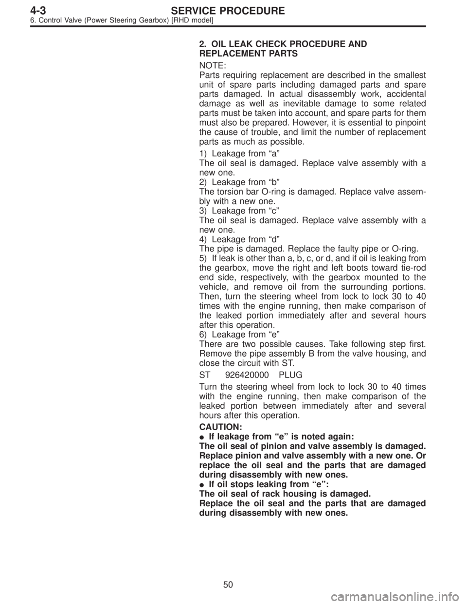
2. OIL LEAK CHECK PROCEDURE AND
REPLACEMENT PARTS
NOTE:
Parts requiring replacement are described in the smallest
unit of spare parts including damaged parts and spare
parts damaged. In actual disassembly work, accidental
damage as well as inevitable damage to some related
parts must be taken into account, and spare parts for them
must also be prepared. However, it is essential to pinpoint
the cause of trouble, and limit the number of replacement
parts as much as possible.
1) Leakage from“a”
The oil seal is damaged. Replace valve assembly with a
new one.
2) Leakage from“b”
The torsion bar O-ring is damaged. Replace valve assem-
bly with a new one.
3) Leakage from“c”
The oil seal is damaged. Replace valve assembly with a
new one.
4) Leakage from“d”
The pipe is damaged. Replace the faulty pipe or O-ring.
5) If leak is other than a, b, c, or d, and if oil is leaking from
the gearbox, move the right and left boots toward tie-rod
end side, respectively, with the gearbox mounted to the
vehicle, and remove oil from the surrounding portions.
Then, turn the steering wheel from lock to lock 30 to 40
times with the engine running, then make comparison of
the leaked portion immediately after and several hours
after this operation.
6) Leakage from“e”
There are two possible causes. Take following step first.
Remove the pipe assembly B from the valve housing, and
close the circuit with ST.
ST 926420000 PLUG
Turn the steering wheel from lock to lock 30 to 40 times
with the engine running, then make comparison of the
leaked portion between immediately after and several
hours after this operation.
CAUTION:
�If leakage from“e”is noted again:
The oil seal of pinion and valve assembly is damaged.
Replace pinion and valve assembly with a new one. Or
replace the oil seal and the parts that are damaged
during disassembly with new ones.
�If oil stops leaking from“e”:
The oil seal of rack housing is damaged.
Replace the oil seal and the parts that are damaged
during disassembly with new ones.
50
4-3SERVICE PROCEDURE
6. Control Valve (Power Steering Gearbox) [RHD model]
Page 1162 of 2890
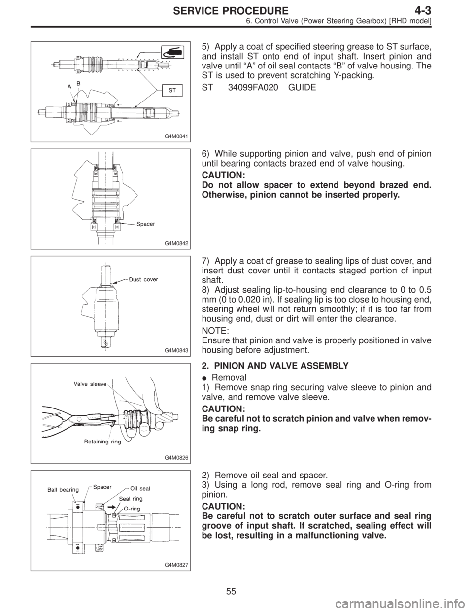
G4M0841
5) Apply a coat of specified steering grease to ST surface,
and install ST onto end of input shaft. Insert pinion and
valve until“A”of oil seal contacts“B”of valve housing. The
ST is used to prevent scratching Y-packing.
ST 34099FA020 GUIDE
G4M0842
6) While supporting pinion and valve, push end of pinion
until bearing contacts brazed end of valve housing.
CAUTION:
Do not allow spacer to extend beyond brazed end.
Otherwise, pinion cannot be inserted properly.
G4M0843
7) Apply a coat of grease to sealing lips of dust cover, and
insert dust cover until it contacts staged portion of input
shaft.
8) Adjust sealing lip-to-housing end clearance to 0 to 0.5
mm (0 to 0.020 in). If sealing lip is too close to housing end,
steering wheel will not return smoothly; if it is too far from
housing end, dust or dirt will enter the clearance.
NOTE:
Ensure that pinion and valve is properly positioned in valve
housing before adjustment.
G4M0826
2. PINION AND VALVE ASSEMBLY
�Removal
1) Remove snap ring securing valve sleeve to pinion and
valve, and remove valve sleeve.
CAUTION:
Be careful not to scratch pinion and valve when remov-
ing snap ring.
G4M0827
2) Remove oil seal and spacer.
3) Using a long rod, remove seal ring and O-ring from
pinion.
CAUTION:
Be careful not to scratch outer surface and seal ring
groove of input shaft. If scratched, sealing effect will
be lost, resulting in a malfunctioning valve.
55
4-3SERVICE PROCEDURE
6. Control Valve (Power Steering Gearbox) [RHD model]
Page 1169 of 2890
G4M0098
7. Pipe Assembly (Power Steering
System) [LHD model]
A: REMOVAL
1) Disconnect battery minus terminal.
G4M0099
2) Lift vehicle and remove jack-up plate.
3) Remove one pipe joint at the center of gearbox, and
connect vinyl hose to pipe and joint. Discharge fluid by
turning steering wheel fully clockwise and counterclock-
wise. Discharge fluid similarly from the other pipe.
CAUTION:
Improper removal and installation of parts often
causes fluid leak trouble. To prevent this, clean the
surrounding portions before disassembly and
reassembly, and pay special attention to keep dirt and
other foreign matter from mating surfaces.
G4M0162
4) Remove clamp E from pipes C and D.
62
4-3SERVICE PROCEDURE
7. Pipe Assembly (Power Steering System) [LHD model]
Page 1174 of 2890
G4M0098
8. Pipe Assembly (Power Steering
System) [RHD model]
A: REMOVAL
1) Disconnect battery negative terminal.
B4M0671A
2) Lift vehicle and remove jack-up plate.
3) Remove one pipe joint at the center of gearbox, and
connect vinyl hose to pipe and joint. Discharge fluid by
turning steering wheel fully clockwise and counterclock-
wise. Discharge fluid similarly from the other pipe.
CAUTION:
Improper removal and installation of parts often
causes fluid leak trouble. To prevent this, clean the
surrounding portions before disassembly and
reassembly, and pay special attention to keep dirt and
other foreign matter from mating surfaces.
B4M0672A
4) Remove clamp E from pipes C and D.
67
4-3SERVICE PROCEDURE
8. Pipe Assembly (Power Steering System) [RHD model]
Page 1188 of 2890
10. Power Steering Fluid
A: RECOMMENDED AIR BLEEDING AND
POWER STEERING FLUID
Recommended power steering fluid Manufacturer
ATF DEXRON II or ATF DEXRON IIEB.P.
CALTEX
CASTROL
MOBIL
SHELL
TEXACO
1) Feed the specified fluid with its level being about 5 cm
(2.0 in) lower than the mouth of tank.
2) Continue to turn steering wheel slowly from lock to lock
until bubbles stop appearing in the tank while keeping the
fluid at that level.
3) In case air is absorbed to deliver bubbles into piping
because the fluid level is lower, leave it about half an hour
and then do the step 2) all over again.
4) Start, and idle the engine.
5) Continue to turn steering wheel slowly from lock to lock
again until bubbles stop appearing in the tank while keep-
ing the fluid at that level.
It is normal that bubbles stop appearing after three times
turning of steering wheel.
6) In case bubbles do not stop appearing in the tank, leave
it about half an hour and then do the step 5) all over again.
7) Stop the engine, and take out safety stands after jack-
ing up vehicle again.
Then lower the vehicle, and idle the engine.
8) Continue to turn steering wheel from lock to lock until
bubbles stop appearing and change of the fluid level is
within 3 mm (0.12 in).
9) In case the following happens, leave it about half an
hour and then do step 8) again.
(1) The fluid level changes over 3 mm (0.12 in).
(2) Bubbles remain on the upper surface of the fluid.
(3) Grinding noise is generated from oil pump.
81
4-3SERVICE PROCEDURE
10. Power Steering Fluid
Page 1189 of 2890
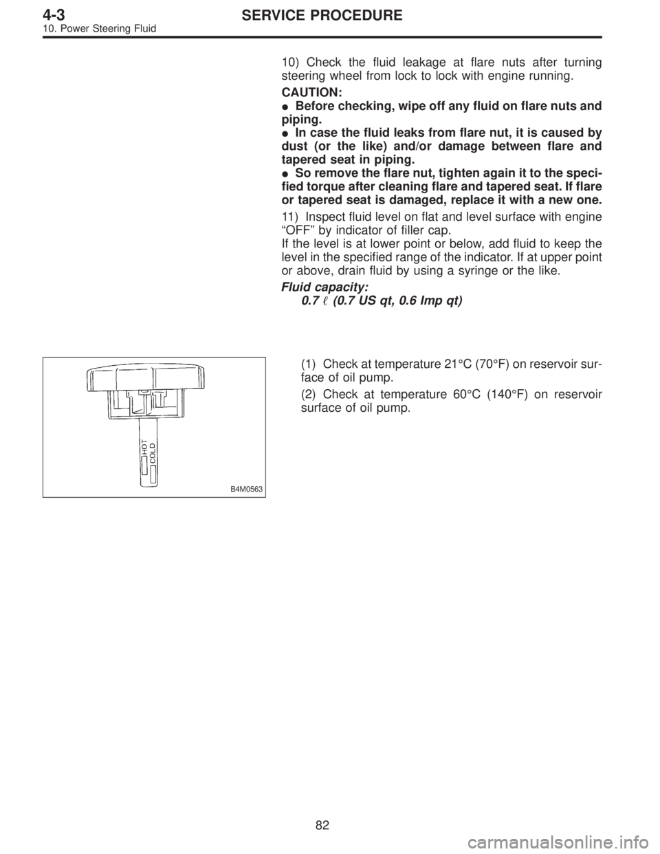
10) Check the fluid leakage at flare nuts after turning
steering wheel from lock to lock with engine running.
CAUTION:
�Before checking, wipe off any fluid on flare nuts and
piping.
�In case the fluid leaks from flare nut, it is caused by
dust (or the like) and/or damage between flare and
tapered seat in piping.
�So remove the flare nut, tighten again it to the speci-
fied torque after cleaning flare and tapered seat. If flare
or tapered seat is damaged, replace it with a new one.
11) Inspect fluid level on flat and level surface with engine
“OFF”by indicator of filler cap.
If the level is at lower point or below, add fluid to keep the
level in the specified range of the indicator. If at upper point
or above, drain fluid by using a syringe or the like.
Fluid capacity:
0.7�(0.7 US qt, 0.6 Imp qt)
B4M0563
(1) Check at temperature 21°C (70°F) on reservoir sur-
face of oil pump.
(2) Check at temperature 60°C (140°F) on reservoir
surface of oil pump.
82
4-3SERVICE PROCEDURE
10. Power Steering Fluid