Page 1107 of 2890
14. Replacement of Front FTJ and BJ
Boots
A: REMOVAL
1) Disconnect ground cable from battery.
2) Jack-up vehicle, support it with safety stands (rigid
rocks), and remove front wheel cap and wheels.
NOTE:
Do not remove axle nut.
3) Remove stabilizer link.
4) Disconnect transverse link from housing.
G4M0279
5) Remove spring pin which secures transmission spindle
to FTJ.
CAUTION:
Use a new spring pin.
6) Remove FTJ and BJ boot from drive shaft.
B: INSTALLATION
1) Install FTJ and BJ boots to drive shaft.
G4M0279
2) Install FTJ on transmission spindle and drive spring pin
into place.
CAUTION:
Always use a new spring pin.
3) Connect transverse link to housing.
4) Install stabilizer link.
53
4-2SERVICE PROCEDURE
14. Replacement of Front FTJ and BJ Boots
Page 1108 of 2890

1. Steering System
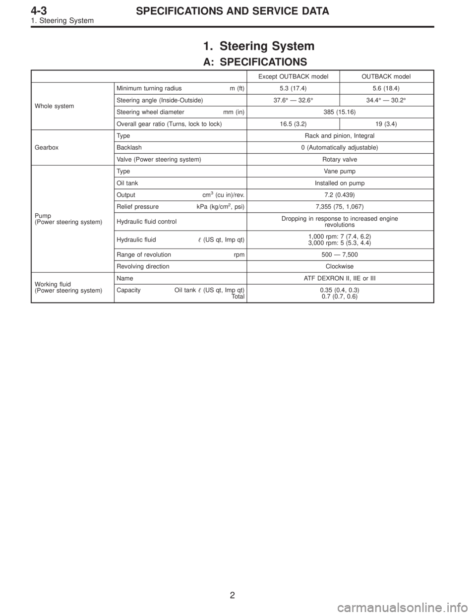
A: SPECIFICATIONS
Except OUTBACK model OUTBACK model
Whole systemMinimum turning radius m (ft) 5.3 (17.4) 5.6 (18.4)
Steering angle (Inside-Outside) 37.6°—32.6°34.4°—30.2°
Steering wheel diameter mm (in) 385 (15.16)
Overall gear ratio (Turns, lock to lock) 16.5 (3.2) 19 (3.4)
GearboxType Rack and pinion, Integral
Backlash 0 (Automatically adjustable)
Valve (Power steering system) Rotary valve
Pump
(Power steering system)Type Vane pump
Oil tank Installed on pump
Output cm
3(cu in)/rev. 7.2 (0.439)
Relief pressure kPa (kg/cm
2, psi) 7,355 (75, 1,067)
Hydraulic fluid controlDropping in response to increased engine
revolutions
Hydraulic fluid�(US qt, Imp qt)1,000 rpm: 7 (7.4, 6.2)
3,000 rpm: 5 (5.3, 4.4)
Range of revolution rpm 500—7,500
Revolving direction Clockwise
Working fluid
(Power steering system)Name ATF DEXRON II, IIE or III
Capacity Oil tank�(US qt, Imp qt)
Total0.35 (0.4, 0.3)
0.7 (0.7, 0.6)
2
4-3SPECIFICATIONS AND SERVICE DATA
1. Steering System
Page 1109 of 2890

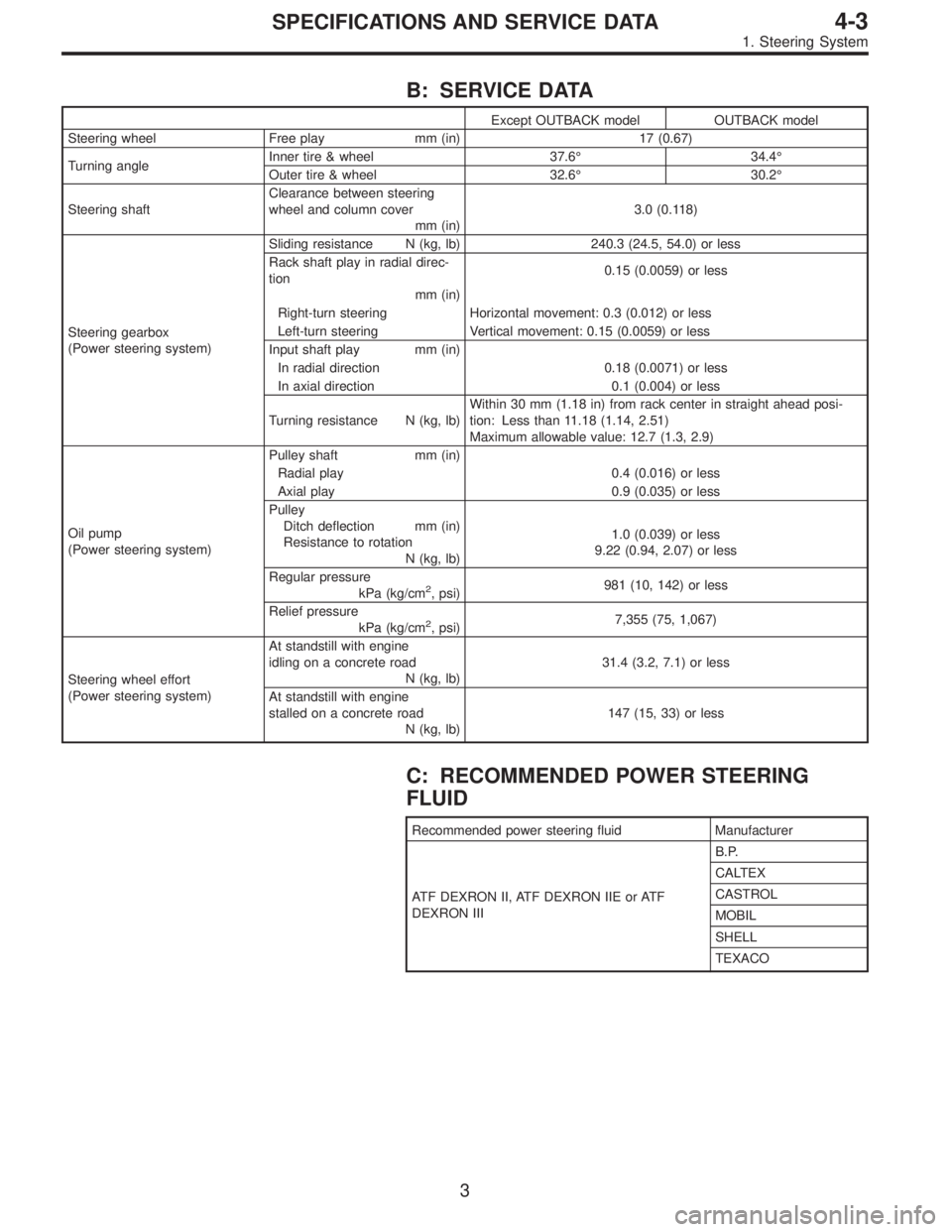
B: SERVICE DATA
Except OUTBACK model OUTBACK model
Steering wheel Free play mm (in) 17 (0.67)
Turning angleInner tire & wheel 37.6°34.4°
Outer tire & wheel 32.6°30.2°
Steering shaftClearance between steering
wheel and column cover
mm (in)3.0 (0.118)
Steering gearbox
(Power steering system)Sliding resistance N (kg, lb) 240.3 (24.5, 54.0) or less
Rack shaft play in radial direc-
tion
mm (in)0.15 (0.0059) or less
Right-turn steering Horizontal movement: 0.3 (0.012) or less
Left-turn steering Vertical movement: 0.15 (0.0059) or less
Input shaft play mm (in)
In radial direction 0.18 (0.0071) or less
In axial direction 0.1 (0.004) or less
Turning resistance N (kg, lb)Within 30 mm (1.18 in) from rack center in straight ahead posi-
tion: Less than 11.18 (1.14, 2.51)
Maximum allowable value: 12.7 (1.3, 2.9)
Oil pump
(Power steering system)Pulley shaft mm (in)
Radial play 0.4 (0.016) or less
Axial play 0.9 (0.035) or less
Pulley
Ditch deflection mm (in)
Resistance to rotation
N (kg, lb)1.0 (0.039) or less
9.22 (0.94, 2.07) or less
Regular pressure
kPa (kg/cm
2, psi)981 (10, 142) or less
Relief pressure
kPa (kg/cm
2, psi)7,355 (75, 1,067)
Steering wheel effort
(Power steering system)At standstill with engine
idling on a concrete road
N (kg, lb)31.4 (3.2, 7.1) or less
At standstill with engine
stalled on a concrete road
N (kg, lb)147 (15, 33) or less
C: RECOMMENDED POWER STEERING
FLUID
Recommended power steering fluid Manufacturer
ATF DEXRON II, ATF DEXRON IIE or ATF
DEXRON IIIB.P.
CALTEX
CASTROL
MOBIL
SHELL
TEXACO
3
4-3SPECIFICATIONS AND SERVICE DATA
1. Steering System
Page 1110 of 2890
1. Steering Wheel and Column (Tilt)
1. WITH AIRBAG MODEL
B4M0551A
�1Bushing
�
2Column shaft
�
3Steering roll connector
�
4Column cover
�
5Steering wheel
�
6Airbag module
Tightening torque: N⋅m (kg-m, ft-lb)
T1: 25±5 (2.5±0.5, 18.1±3.6)
T2: 34±5 (3.5±0.5, 25.3±3.6)
4
4-3COMPONENT PARTS
1. Steering Wheel and Column (Tilt)
Page 1116 of 2890
1. Supplemental Restraint System
“Airbag”
Airbag system wiring harness is routed near the steering
wheel, steering shaft and column.
WARNING:
�All Airbag system wiring harness and connectors
are colored yellow. Do not use electrical test equip-
ment on these circuit.
�Be careful not to damage Airbag system wiring har-
ness when servicing the steering wheel, steering shaft
and column.
2. Tilt Steering Column
B4M0554A
Tightening torque: N⋅m (kg-m, ft-lb)
T1: 24±3 (2.4±0.3, 17.4±2.2)
T2: 25±5 (2.5±0.5, 18.1±3.6)
A: REMOVAL
1) Disconnect battery minus terminal.
2) Lift-up vehicle.
3) Remove airbag module. (with airbag model)
5-5 [W3A1].>
WARNING:
Always refer to“5-5 Supplemental Restraint System”
before performing airbag module service (if so
equipped).
10
4-3SERVICE PROCEDURE
1. Supplemental Restraint System“Airbag”- 2. Tilt Steering Column
Page 1117 of 2890
1. Supplemental Restraint System
“Airbag”
Airbag system wiring harness is routed near the steering
wheel, steering shaft and column.
WARNING:
�All Airbag system wiring harness and connectors
are colored yellow. Do not use electrical test equip-
ment on these circuit.
�Be careful not to damage Airbag system wiring har-
ness when servicing the steering wheel, steering shaft
and column.
2. Tilt Steering Column
B4M0554A
Tightening torque: N⋅m (kg-m, ft-lb)
T1: 24±3 (2.4±0.3, 17.4±2.2)
T2: 25±5 (2.5±0.5, 18.1±3.6)
A: REMOVAL
1) Disconnect battery minus terminal.
2) Lift-up vehicle.
3) Remove airbag module. (with airbag model)
5-5 [W3A1].>
WARNING:
Always refer to“5-5 Supplemental Restraint System”
before performing airbag module service (if so
equipped).
10
4-3SERVICE PROCEDURE
1. Supplemental Restraint System“Airbag”- 2. Tilt Steering Column
Page 1118 of 2890

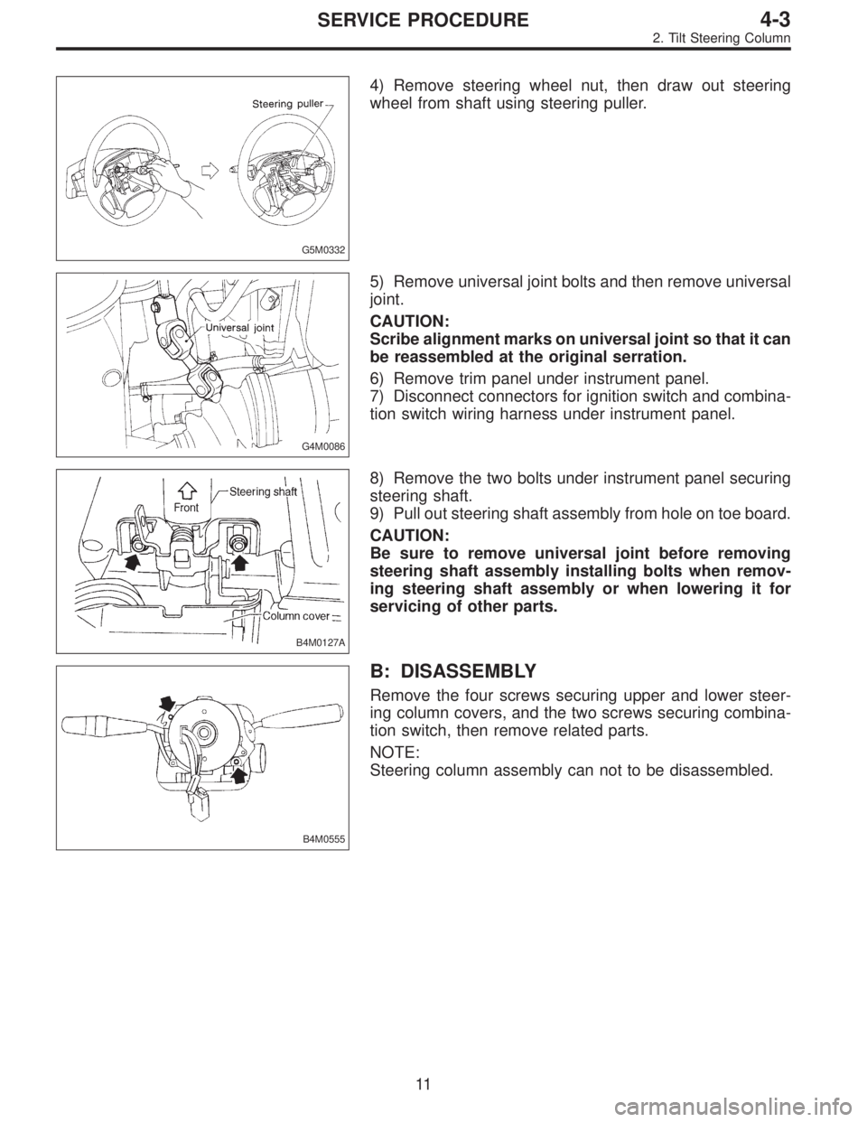
G5M0332
4) Remove steering wheel nut, then draw out steering
wheel from shaft using steering puller.
G4M0086
5) Remove universal joint bolts and then remove universal
joint.
CAUTION:
Scribe alignment marks on universal joint so that it can
be reassembled at the original serration.
6) Remove trim panel under instrument panel.
7) Disconnect connectors for ignition switch and combina-
tion switch wiring harness under instrument panel.
B4M0127A
8) Remove the two bolts under instrument panel securing
steering shaft.
9) Pull out steering shaft assembly from hole on toe board.
CAUTION:
Be sure to remove universal joint before removing
steering shaft assembly installing bolts when remov-
ing steering shaft assembly or when lowering it for
servicing of other parts.
B4M0555
B: DISASSEMBLY
Remove the four screws securing upper and lower steer-
ing column covers, and the two screws securing combina-
tion switch, then remove related parts.
NOTE:
Steering column assembly can not to be disassembled.
11
4-3SERVICE PROCEDURE
2. Tilt Steering Column
Page 1120 of 2890

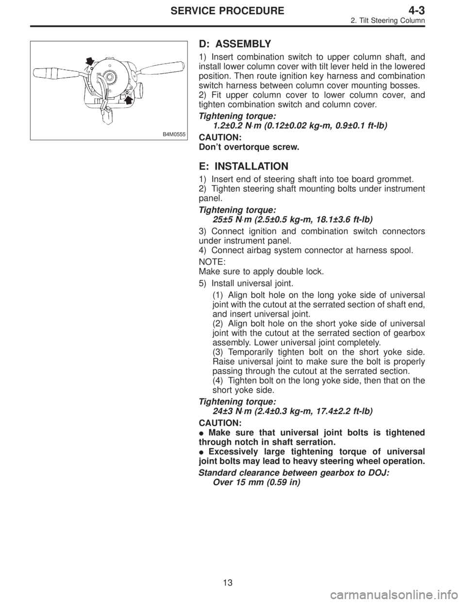
B4M0555
D: ASSEMBLY
1) Insert combination switch to upper column shaft, and
install lower column cover with tilt lever held in the lowered
position. Then route ignition key harness and combination
switch harness between column cover mounting bosses.
2) Fit upper column cover to lower column cover, and
tighten combination switch and column cover.
Tightening torque:
1.2±0.2 N⋅m (0.12±0.02 kg-m, 0.9±0.1 ft-lb)
CAUTION:
Don’t overtorque screw.
E: INSTALLATION
1) Insert end of steering shaft into toe board grommet.
2) Tighten steering shaft mounting bolts under instrument
panel.
Tightening torque:
25±5 N⋅m (2.5±0.5 kg-m, 18.1±3.6 ft-lb)
3) Connect ignition and combination switch connectors
under instrument panel.
4) Connect airbag system connector at harness spool.
NOTE:
Make sure to apply double lock.
5) Install universal joint.
(1) Align bolt hole on the long yoke side of universal
joint with the cutout at the serrated section of shaft end,
and insert universal joint.
(2) Align bolt hole on the short yoke side of universal
joint with the cutout at the serrated section of gearbox
assembly. Lower universal joint completely.
(3) Temporarily tighten bolt on the short yoke side.
Raise universal joint to make sure the bolt is properly
passing through the cutout at the serrated section.
(4) Tighten bolt on the long yoke side, then that on the
short yoke side.
Tightening torque:
24±3 N⋅m (2.4±0.3 kg-m, 17.4±2.2 ft-lb)
CAUTION:
�Make sure that universal joint bolts is tightened
through notch in shaft serration.
�Excessively large tightening torque of universal
joint bolts may lead to heavy steering wheel operation.
Standard clearance between gearbox to DOJ:
Over 15 mm (0.59 in)
13
4-3SERVICE PROCEDURE
2. Tilt Steering Column