Page 1324 of 2890
D: ABS SEQUENCE CONTROL
1) Under the ABS sequence control, after the hydraulic
unit solenoid valve is driven, the operation of the hydraulic
unit can be checked by means of the brake tester or pres-
sure gauge.
2) ABS sequence control can be started by diagnosis con-
nector or select monitor.
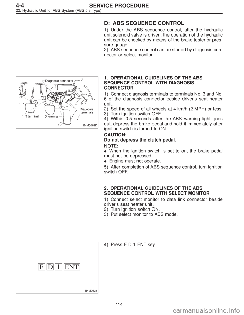
B4M0082D
1. OPERATIONAL GUIDELINES OF THE ABS
SEQUENCE CONTROL WITH DIAGNOSIS
CONNECTOR
1) Connect diagnosis terminals to terminals No. 3 and No.
6 of the diagnosis connector beside driver’s seat heater
unit.
2) Set the speed of all wheels at 4 km/h (2 MPH) or less.
3) Turn ignition switch OFF.
4) Within 0.5 seconds after the ABS warning light goes
out, depress the brake pedal and hold it immediately after
ignition switch is turned to ON.
CAUTION:
Do not depress the clutch pedal.
NOTE:
�When the ignition switch is set to on, the brake pedal
must not be depressed.
�Engine must not operate.
5) After completion of ABS sequence control, turn ignition
switch OFF.
2. OPERATIONAL GUIDELINES OF THE ABS
SEQUENCE CONTROL WITH SELECT MONITOR
1) Connect select monitor to data link connector beside
driver’s seat heater unit.
2) Turn ignition switch ON.
3) Put select monitor to ABS mode.
B4M0635
4) PressFD1ENTkey.
11 4
4-4SERVICE PROCEDURE
22. Hydraulic Unit for ABS System (ABS 5.3 Type)
Page 1326 of 2890
3. CONDITIONS FOR COMPLETION OF ABS
SEQUENCE CONTROL
When the following conditions develop, the ABS sequence
control stops and ABS operation is returned to the normal
control mode.
1) When the speed of at least one wheel reaches 10 km/h
(6 MPH).
2) When terminal No. 3 or No. 6 are separated from diag-
nosis terminals. (When select monitor is not used.)
3) When the brake pedal is released during sequence con-
trol and the braking lamp switch is set to off.
4) When brake pedal is depressed after ignition key is
turned to ON, and before ABS warning light goes out.
(When select monitor is not used.)
5) When brake pedal is not depressed after ignition key is
turned to ON, and within 0.5 seconds after ABS warning
light goes out. (When select monitor is not used.)
6) After completion of the sequence control.
7) When malfunction is detected. (When select monitor is
used.)
11 6
4-4SERVICE PROCEDURE
22. Hydraulic Unit for ABS System (ABS 5.3 Type)
Page 1335 of 2890
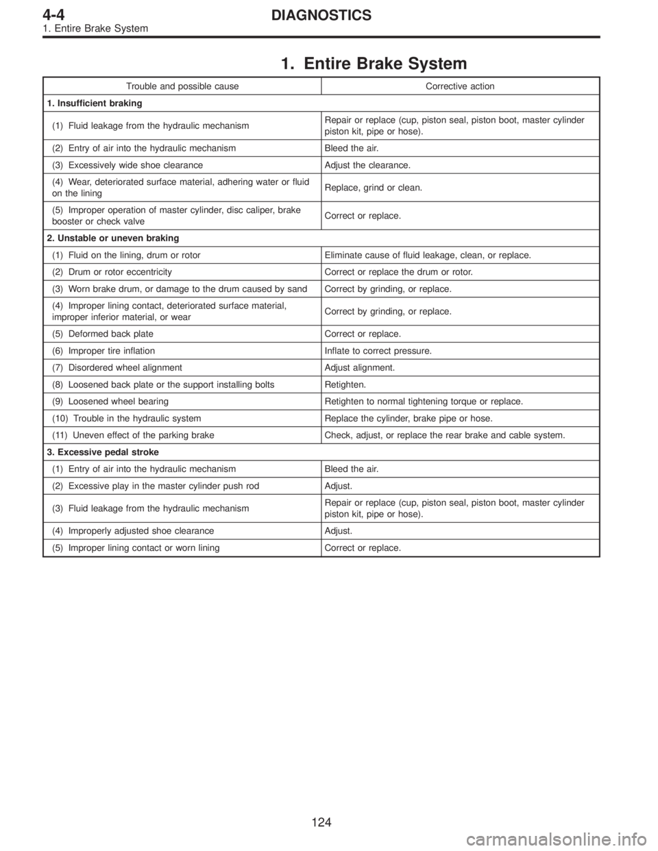
1. Entire Brake System
Trouble and possible cause Corrective action
1. Insufficient braking
(1) Fluid leakage from the hydraulic mechanismRepair or replace (cup, piston seal, piston boot, master cylinder
piston kit, pipe or hose).
(2) Entry of air into the hydraulic mechanism Bleed the air.
(3) Excessively wide shoe clearance Adjust the clearance.
(4) Wear, deteriorated surface material, adhering water or fluid
on the liningReplace, grind or clean.
(5) Improper operation of master cylinder, disc caliper, brake
booster or check valveCorrect or replace.
2. Unstable or uneven braking
(1) Fluid on the lining, drum or rotor Eliminate cause of fluid leakage, clean, or replace.
(2) Drum or rotor eccentricity Correct or replace the drum or rotor.
(3) Worn brake drum, or damage to the drum caused by sand Correct by grinding, or replace.
(4) Improper lining contact, deteriorated surface material,
improper inferior material, or wearCorrect by grinding, or replace.
(5) Deformed back plate Correct or replace.
(6) Improper tire inflation Inflate to correct pressure.
(7) Disordered wheel alignment Adjust alignment.
(8) Loosened back plate or the support installing bolts Retighten.
(9) Loosened wheel bearing Retighten to normal tightening torque or replace.
(10) Trouble in the hydraulic system Replace the cylinder, brake pipe or hose.
(11) Uneven effect of the parking brake Check, adjust, or replace the rear brake and cable system.
3. Excessive pedal stroke
(1) Entry of air into the hydraulic mechanism Bleed the air.
(2) Excessive play in the master cylinder push rod Adjust.
(3) Fluid leakage from the hydraulic mechanismRepair or replace (cup, piston seal, piston boot, master cylinder
piston kit, pipe or hose).
(4) Improperly adjusted shoe clearance Adjust.
(5) Improper lining contact or worn lining Correct or replace.
124
4-4DIAGNOSTICS
1. Entire Brake System
Page 1336 of 2890
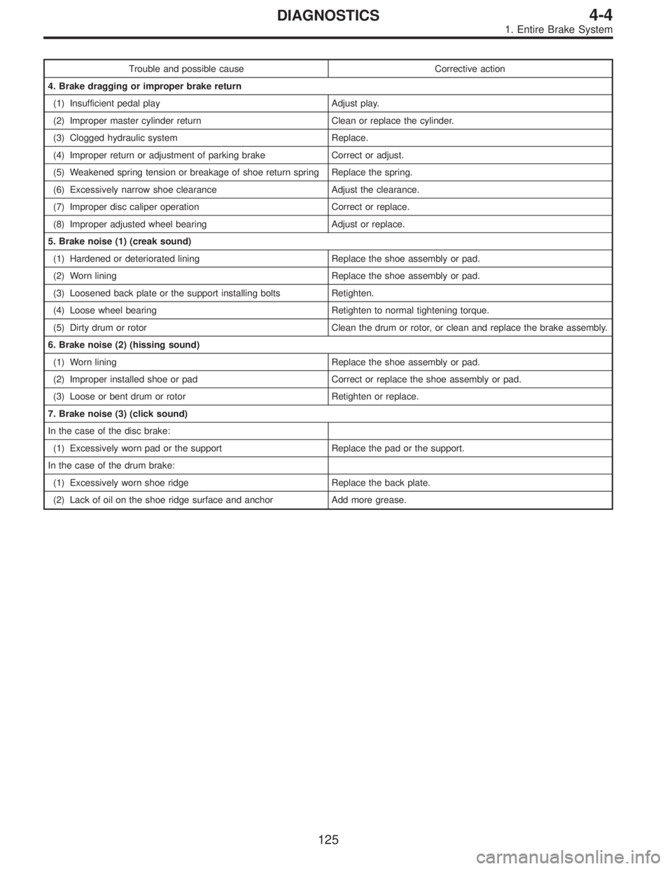
Trouble and possible cause Corrective action
4. Brake dragging or improper brake return
(1) Insufficient pedal play Adjust play.
(2) Improper master cylinder return Clean or replace the cylinder.
(3) Clogged hydraulic system Replace.
(4) Improper return or adjustment of parking brake Correct or adjust.
(5) Weakened spring tension or breakage of shoe return spring Replace the spring.
(6) Excessively narrow shoe clearance Adjust the clearance.
(7) Improper disc caliper operation Correct or replace.
(8) Improper adjusted wheel bearing Adjust or replace.
5. Brake noise (1) (creak sound)
(1) Hardened or deteriorated lining Replace the shoe assembly or pad.
(2) Worn lining Replace the shoe assembly or pad.
(3) Loosened back plate or the support installing bolts Retighten.
(4) Loose wheel bearing Retighten to normal tightening torque.
(5) Dirty drum or rotor Clean the drum or rotor, or clean and replace the brake assembly.
6. Brake noise (2) (hissing sound)
(1) Worn lining Replace the shoe assembly or pad.
(2) Improper installed shoe or pad Correct or replace the shoe assembly or pad.
(3) Loose or bent drum or rotor Retighten or replace.
7. Brake noise (3) (click sound)
In the case of the disc brake:
(1) Excessively worn pad or the support Replace the pad or the support.
In the case of the drum brake:
(1) Excessively worn shoe ridge Replace the back plate.
(2) Lack of oil on the shoe ridge surface and anchor Add more grease.
125
4-4DIAGNOSTICS
1. Entire Brake System
Page 1478 of 2890
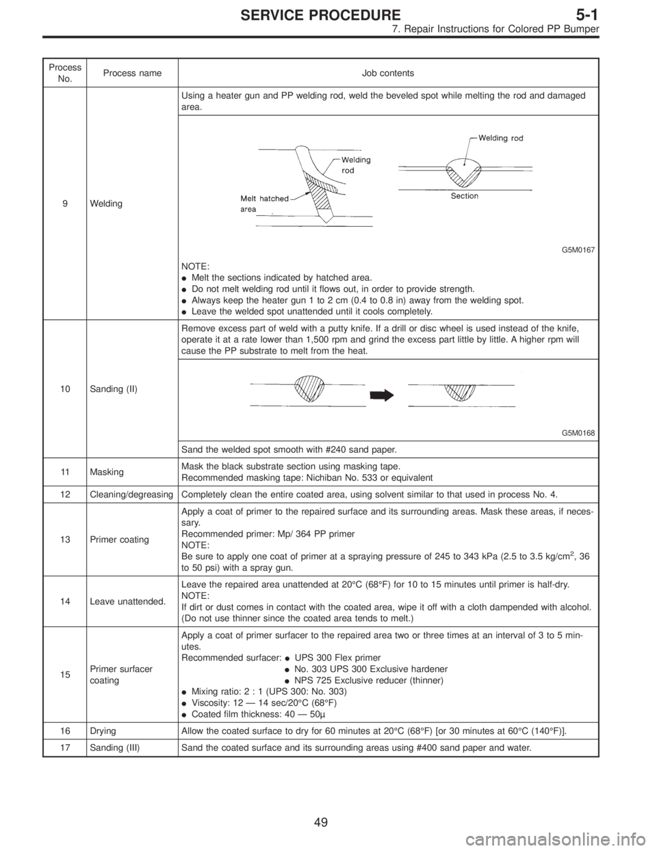
Process
No.Process name Job contents
9 WeldingUsing a heater gun and PP welding rod, weld the beveled spot while melting the rod and damaged
area.
G5M0167
NOTE:
�Melt the sections indicated by hatched area.
�Do not melt welding rod until it flows out, in order to provide strength.
�Always keep the heater gun 1 to 2 cm (0.4 to 0.8 in) away from the welding spot.
�Leave the welded spot unattended until it cools completely.
10 Sanding (II)Remove excess part of weld with a putty knife. If a drill or disc wheel is used instead of the knife,
operate it at a rate lower than 1,500 rpm and grind the excess part little by little. A higher rpm will
cause the PP substrate to melt from the heat.
G5M0168
Sand the welded spot smooth with #240 sand paper.
11 MaskingMask the black substrate section using masking tape.
Recommended masking tape: Nichiban No. 533 or equivalent
12 Cleaning/degreasing Completely clean the entire coated area, using solvent similar to that used in process No. 4.
13 Primer coatingApply a coat of primer to the repaired surface and its surrounding areas. Mask these areas, if neces-
sary.
Recommended primer: Mp/ 364 PP primer
NOTE:
Be sure to apply one coat of primer at a spraying pressure of 245 to 343 kPa (2.5 to 3.5 kg/cm
2,36
to 50 psi) with a spray gun.
14 Leave unattended.Leave the repaired area unattended at 20°C (68°F) for 10 to 15 minutes until primer is half-dry.
NOTE:
If dirt or dust comes in contact with the coated area, wipe it off with a cloth dampended with alcohol.
(Do not use thinner since the coated area tends to melt.)
15Primer surfacer
coatingApply a coat of primer surfacer to the repaired area two or three times at an interval of 3 to 5 min-
utes.
Recommended surfacer:�UPS 300 Flex primer
�No. 303 UPS 300 Exclusive hardener
�NPS 725 Exclusive reducer (thinner)
�Mixing ratio:2:1(UPS 300: No. 303)
�Viscosity: 12—14 sec/20°C (68°F)
�Coated film thickness: 40—50µ
16 Drying Allow the coated surface to dry for 60 minutes at 20°C (68°F) [or 30 minutes at 60°C (140°F)].
17 Sanding (III) Sand the coated surface and its surrounding areas using #400 sand paper and water.
49
5-1SERVICE PROCEDURE
7. Repair Instructions for Colored PP Bumper
Page 1577 of 2890
6. COMBINATION SWITCH
Inspection standard:
�A vehicle damaged in a collision (regardless of whether
or not airbag is deployed).
�The designated trouble code is output during self-diag-
nosis. (Refer to“Diagnostics”Section.)
Replacement standard:
�Combination switch or steering roll connector is
deformed or cracked.
B5M0095
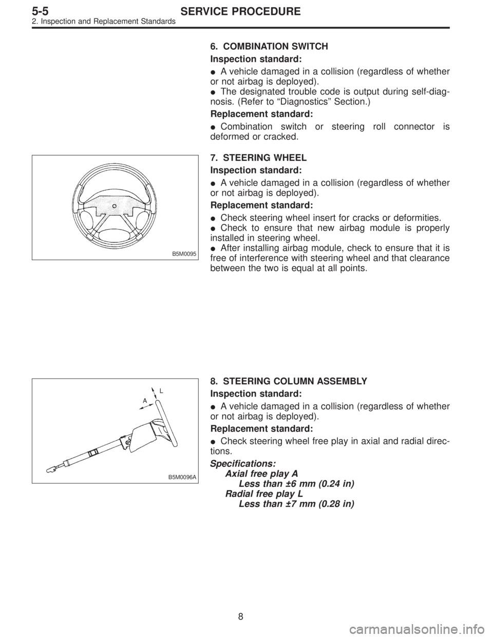
7. STEERING WHEEL
Inspection standard:
�A vehicle damaged in a collision (regardless of whether
or not airbag is deployed).
Replacement standard:
�Check steering wheel insert for cracks or deformities.
�Check to ensure that new airbag module is properly
installed in steering wheel.
�After installing airbag module, check to ensure that it is
free of interference with steering wheel and that clearance
between the two is equal at all points.
B5M0096A
8. STEERING COLUMN ASSEMBLY
Inspection standard:
�A vehicle damaged in a collision (regardless of whether
or not airbag is deployed).
Replacement standard:
�Check steering wheel free play in axial and radial direc-
tions.
Specifications:
Axial free play A
Less than ±6 mm (0.24 in)
Radial free play L
Less than ±7 mm (0.28 in)
8
5-5SERVICE PROCEDURE
2. Inspection and Replacement Standards
Page 1581 of 2890
A: REMOVAL
1. DRIVER SIDE
1) Set front wheels in straight ahead position.
2) Turn ignition switch off.
3) Disconnect ground cable from battery and wait for at
least 20 seconds before starting work.
H5M0662A
4) Using TORX®BIT T30, remove two TORX®bolts.
H5M0664
5) Disconnect airbag connector on back of airbag module.
6) Refer to“CAUTION”for handling of a removed airbag
module.
2. PASSENGER SIDE
1) Remove instrument panel.
12
5-5SERVICE PROCEDURE
3. Airbag Module
Page 1582 of 2890
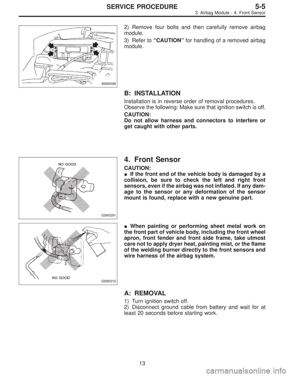
B5M0098
2) Remove four bolts and then carefully remove airbag
module.
3) Refer to“CAUTION”for handling of a removed airbag
module.
B: INSTALLATION
Installation is in reverse order of removal procedures.
Observe the following: Make sure that ignition switch is off.
CAUTION:
Do not allow harness and connectors to interfere or
get caught with other parts.
G5M0291
4. Front Sensor
CAUTION:
�If the front end of the vehicle body is damaged by a
collision, be sure to check the left and right front
sensors, even if the airbag was not inflated. If any dam-
age to the sensor or any deformation of the sensor
mount is found, replace with a new genuine part.
G5M0310
�When painting or performing sheet metal work on
the front part of vehicle body, including the front wheel
apron, front fender and front side frame, take utmost
care not to apply dryer heat, painting mist, or the flame
of the welding burner directly to the front sensors and
wire harness of the airbag system.
A: REMOVAL
1) Turn ignition switch off.
2) Disconnect ground cable from battery and wait for at
least 20 seconds before starting work.
13
5-5SERVICE PROCEDURE
3. Airbag Module - 4. Front Sensor