Page 1889 of 2890
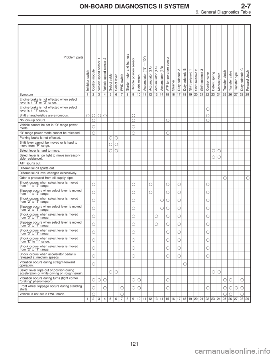
Problem parts
Inhibitor switch
Control module
Vehicle speed sensor 1
Vehicle speed sensor 2
Select cable
Select lever
FWD switch
Starter motor and harness
Throttle position sensor
Hold switch
Accumulator (“N”—“D”)
Accumulator (2A)
Accumulator (4A)
Accumulator (3R)
ATF temperature sensor
Strainer
Duty solenoid A
Duty solenoid B
Shift solenoid 1
Shift solenoid 2
Shift solenoid 3
Control valve
Detent spring
Manual plate
Transfer clutch
Transfer valve
Transfer pipe
Duty solenoid C
Forward clutch
Symptom1234567891011121314151617181920212223242526272829
Engine brake is not effected when select
lever is in“3”or“2”range.
Engine brake is not effected when select
lever is in“1”range.�
Shift characteristics are erroneous.���� � �
No lock-up occurs.����
Vehicle cannot be set in“D”range power
mode.��
“D”range power mode cannot be released.���
Parking brake is not effected.��
Shift lever cannot be moved or is hard to
move from“P”range.��
Select lever is hard to move.�� ��
Select lever is too light to move (unreason-
able resistance).��
ATF spurts out.
Differential oil spurts out.
Differential oil level changes excessively.
Odor is produced from oil supply pipe.��
Shock occurs when select lever is moved
from“1”to“2”range.� ���� �
Slippage occurs when select lever is moved
from“1”to“2”range.� ���� �
Shock occurs when select lever is moved
from“2”to“3”range.������
Slippage occurs when select lever is moved
from“2”to“3”range.������
Shock occurs when select lever is moved
from“3”to“4”range.� � ��� �
Slippage occurs when select lever is moved
from“3”to“4”range.� � ��� �
Shock occurs when select lever is moved
from“3”to“2”range.�����
Shock occurs when select lever is moved
from“D”to“1”range.�����
Shock occurs when select lever is moved
from“2”to“1”range.�����
Shock occurs when accelerator pedal is
released at medium speeds.�����
Vibration occurs during straight-forward
operation.��
Select lever slips out of position during
acceleration or while driving on rough terrain.�� ��
Vibration occurs during turns (tight corner
“braking”phenomenon).��� �� � �� �
Front wheel slippage occurs during standing
starts.� � � �� � � ����
Vehicle is not set in FWD mode.�� ���
1234567891011121314151617181920212223242526272829
121
2-7ON-BOARD DIAGNOSTICS II SYSTEM
9. General Diagnostics Table
Page 1890 of 2890
Overrunning clutch
Drive pinion
Crown gear
Axle shaft
Differential gear
Final gear
Seal pipe
Oil pump
High clutch
Band brake
Low & reverse clutch
Reverse clutch
One-way clutch (1-2)
One-way clutch (3-4)
Double oil seal
Input shaft
Output shaft
Planetary gear
Reduction gear
Drive plate
Torque converter one-way clutch
Lock-up facing
Lock-up damper
ATF deterioration
ATF level too high or too low
Differential gear oil level too high or too low
Engine performance
Engine speed signal
Parking brake mechanism
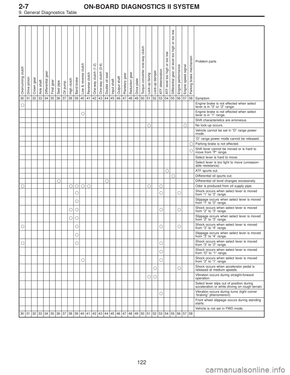
Problem parts
30 31 32 33 34 35 36 37 38 39 40 41 42 43 44 45 46 47 48 49 50 51 52 53 54 55 56 57 58 Symptom
�Engine brake is not effected when select
lever is in“3”or“2”range.
�Engine brake is not effected when select
lever is in“1”range.
Shift characteristics are erroneous.
��No lock-up occurs.
Vehicle cannot be set in“D”range power
mode.
“D”range power mode cannot be released.
�Parking brake is not effected.
�Shift lever cannot be moved or is hard to
move from“P”range.
Select lever is hard to move.
Select lever is too light to move (unreason-
able resistance).
�ATF spurts out.
�Differential oil spurts out.
��Differential oil level changes excessively.
� ���� � �Odor is produced from oil supply pipe.
���Shock occurs when select lever is moved
from“1”to“2”range.
�Slippage occurs when select lever is moved
from“1”to“2”range.
�� � �Shock occurs when select lever is moved
from“2”to“3”range.
��Slippage occurs when select lever is moved
from“2”to“3”range.
�� ��Shock occurs when select lever is moved
from“3”to“4”range.
�Slippage occurs when select lever is moved
from“3”to“4”range.
�� �Shock occurs when select lever is moved
from“3”to“2”range.
�Shock occurs when select lever is moved
from“D”to“1”range.
��Shock occurs when select lever is moved
from“2”to“1”range.
��Shock occurs when accelerator pedal is
released at medium speeds.
��Vibration occurs during straight-forward
operation.
Select lever slips out of position during
acceleration or while driving on rough terrain.
�Vibration occurs during turns (tight corner
“braking”phenomenon).
Front wheel slippage occurs during standing
starts.
Vehicle is not set in FWD mode.
30 31 32 33 34 35 36 37 38 39 40 41 42 43 44 45 46 47 48 49 50 51 52 53 54 55 56 57 58
122
2-7ON-BOARD DIAGNOSTICS II SYSTEM
9. General Diagnostics Table
Page 2078 of 2890
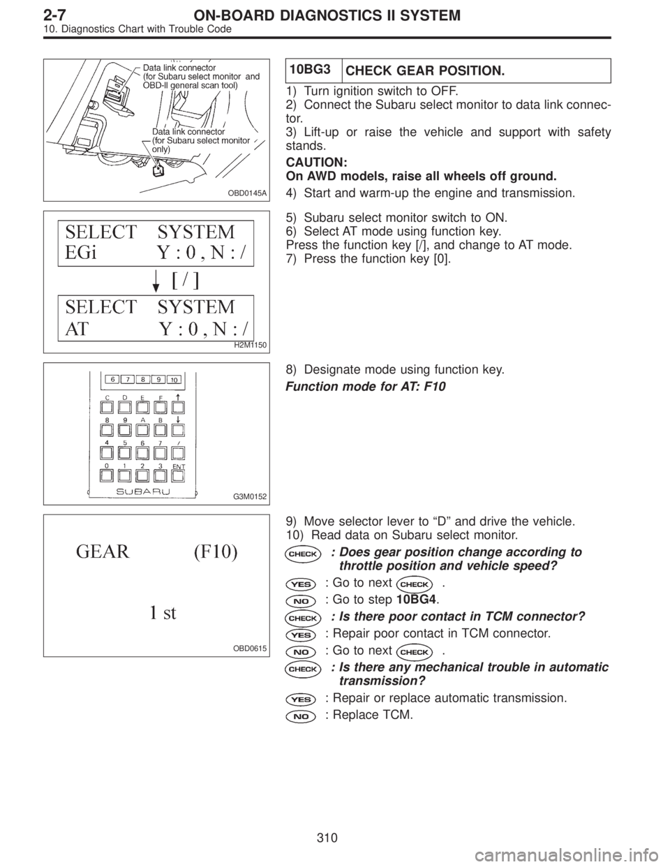
OBD0145A
10BG3
CHECK GEAR POSITION.
1) Turn ignition switch to OFF.
2) Connect the Subaru select monitor to data link connec-
tor.
3) Lift-up or raise the vehicle and support with safety
stands.
CAUTION:
On AWD models, raise all wheels off ground.
4) Start and warm-up the engine and transmission.
H2M1150
5) Subaru select monitor switch to ON.
6) Select AT mode using function key.
Press the function key [/], and change to AT mode.
7) Press the function key [0].
G3M0152
8) Designate mode using function key.
Function mode for AT: F10
OBD0615
9) Move selector lever to“D”and drive the vehicle.
10) Read data on Subaru select monitor.
: Does gear position change according to
throttle position and vehicle speed?
: Go to next.
: Go to step10BG4.
: Is there poor contact in TCM connector?
: Repair poor contact in TCM connector.
: Go to next.
: Is there any mechanical trouble in automatic
transmission?
: Repair or replace automatic transmission.
: Replace TCM.
310
2-7ON-BOARD DIAGNOSTICS II SYSTEM
10. Diagnostics Chart with Trouble Code
Page 2132 of 2890
OBD0513A
10BT2
CHECK INPUT SIGNAL FOR TCM.
1) Connect connector to TCM and CCM.
2) Lift-up the vehicle or set the vehicle on free rollers.
CAUTION:
On AWD models, raise all wheels off ground.
3) Start the engine.
4) Cruise control main switch to ON.
5) TCS OFF switch to ON. (with TCS models only)
6) Move selector lever to“D”and slowly increase vehicle
speed to 50 km/h (31 MPH).
7) Cruise control set switch to ON.
8) Measure voltage between TCM and chassis ground.
: Connector & terminal
(B56) No. 3 (+)—Chassis ground (�):
Is the voltage less than 1 V?
: Go to next.
: Check cruise control set circuit.
[T7A0].>
: Is there poor contact in TCM connector?
: Repair poor contact in TCM connector.
: Replace TCM.
364
2-7ON-BOARD DIAGNOSTICS II SYSTEM
10. Diagnostics Chart with Trouble Code
Page 2161 of 2890
OBD0607A
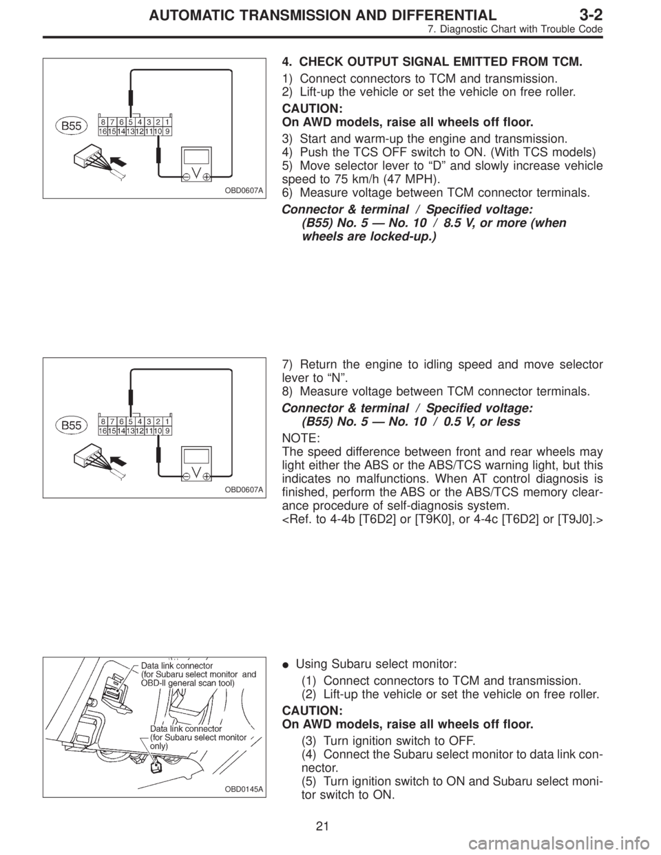
4. CHECK OUTPUT SIGNAL EMITTED FROM TCM.
1) Connect connectors to TCM and transmission.
2) Lift-up the vehicle or set the vehicle on free roller.
CAUTION:
On AWD models, raise all wheels off floor.
3) Start and warm-up the engine and transmission.
4) Push the TCS OFF switch to ON. (With TCS models)
5) Move selector lever to“D”and slowly increase vehicle
speed to 75 km/h (47 MPH).
6) Measure voltage between TCM connector terminals.
Connector & terminal / Specified voltage:
(B55) No. 5—No. 10 / 8.5 V, or more (when
wheels are locked-up.)
OBD0607A
7) Return the engine to idling speed and move selector
lever to“N”.
8) Measure voltage between TCM connector terminals.
Connector & terminal / Specified voltage:
(B55) No. 5—No. 10 / 0.5 V, or less
NOTE:
The speed difference between front and rear wheels may
light either the ABS or the ABS/TCS warning light, but this
indicates no malfunctions. When AT control diagnosis is
finished, perform the ABS or the ABS/TCS memory clear-
ance procedure of self-diagnosis system.
OBD0145A
�Using Subaru select monitor:
(1) Connect connectors to TCM and transmission.
(2) Lift-up the vehicle or set the vehicle on free roller.
CAUTION:
On AWD models, raise all wheels off floor.
(3) Turn ignition switch to OFF.
(4) Connect the Subaru select monitor to data link con-
nector.
(5) Turn ignition switch to ON and Subaru select moni-
tor switch to ON.
21
3-2AUTOMATIC TRANSMISSION AND DIFFERENTIAL
7. Diagnostic Chart with Trouble Code
Page 2162 of 2890
OBD0417
(6) Start and warm-up the engine and transmission.
(7) Push the TCS OFF switch to ON. (With TCS mod-
els)
(8) Designate mode using function key.
Function mode: F12
(9) Move selector lever to“D”and slowly increase
vehicle speed to 75 km/h (47 MPH).
(10) Read data on Subaru select monitor.
SPECIFIED DATA:
�95% (Wheel locked-up)
�5% (Released)
NOTE:
The speed difference between front and rear wheels may
light either the ABS or the ABS/TCS warning light, but this
indicates no malfunctions. When AT control diagnosis is
finished, perform the ABS or the ABS/TCS memory clear-
ance procedure of self-diagnosis system.
22
3-2AUTOMATIC TRANSMISSION AND DIFFERENTIAL
7. Diagnostic Chart with Trouble Code
Page 2164 of 2890
OBD0455A
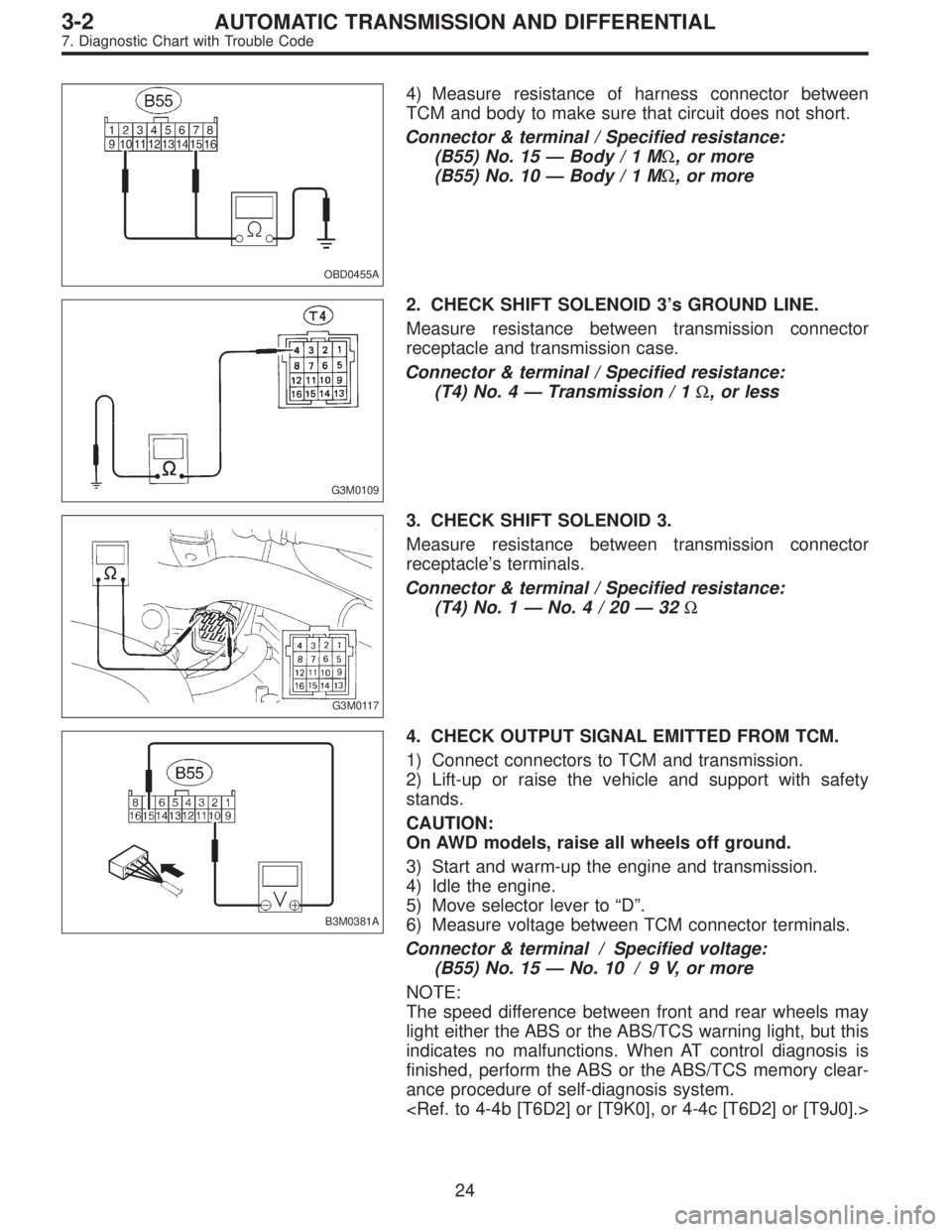
4) Measure resistance of harness connector between
TCM and body to make sure that circuit does not short.
Connector & terminal / Specified resistance:
(B55) No. 15—Body/1MΩ, or more
(B55) No. 10—Body/1MΩ, or more
G3M0109
2. CHECK SHIFT SOLENOID 3’s GROUND LINE.
Measure resistance between transmission connector
receptacle and transmission case.
Connector & terminal / Specified resistance:
(T4) No. 4—Transmission / 1Ω, or less
G3M0117
3. CHECK SHIFT SOLENOID 3.
Measure resistance between transmission connector
receptacle’s terminals.
Connector & terminal / Specified resistance:
(T4) No. 1—No.4/20—32Ω
B3M0381A
4. CHECK OUTPUT SIGNAL EMITTED FROM TCM.
1) Connect connectors to TCM and transmission.
2) Lift-up or raise the vehicle and support with safety
stands.
CAUTION:
On AWD models, raise all wheels off ground.
3) Start and warm-up the engine and transmission.
4) Idle the engine.
5) Move selector lever to“D”.
6) Measure voltage between TCM connector terminals.
Connector & terminal / Specified voltage:
(B55) No. 15—No. 10 / 9 V, or more
NOTE:
The speed difference between front and rear wheels may
light either the ABS or the ABS/TCS warning light, but this
indicates no malfunctions. When AT control diagnosis is
finished, perform the ABS or the ABS/TCS memory clear-
ance procedure of self-diagnosis system.
24
3-2AUTOMATIC TRANSMISSION AND DIFFERENTIAL
7. Diagnostic Chart with Trouble Code
Page 2166 of 2890
OBD0447A
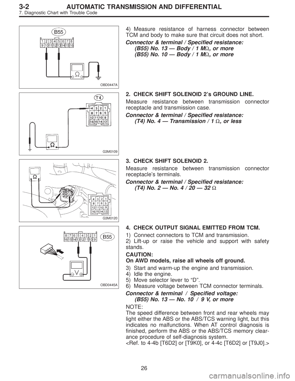
4) Measure resistance of harness connector between
TCM and body to make sure that circuit does not short.
Connector & terminal / Specified resistance:
(B55) No. 13—Body/1MΩ, or more
(B55) No. 10—Body/1MΩ, or more
G3M0109
2. CHECK SHIFT SOLENOID 2’s GROUND LINE.
Measure resistance between transmission connector
receptacle and transmission case.
Connector & terminal / Specified resistance:
(T4) No. 4—Transmission / 1Ω, or less
G3M0120
3. CHECK SHIFT SOLENOID 2.
Measure resistance between transmission connector
receptacle’s terminals.
Connector & terminal / Specified resistance:
(T4) No. 2—No.4/20—32Ω
OBD0445A
4. CHECK OUTPUT SIGNAL EMITTED FROM TCM.
1) Connect connectors to TCM and transmission.
2) Lift-up or raise the vehicle and support with safety
stands.
CAUTION:
On AWD models, raise all wheels off ground.
3) Start and warm-up the engine and transmission.
4) Idle the engine.
5) Move selector lever to“D”.
6) Measure voltage between TCM connector terminals.
Connector & terminal / Specified voltage:
(B55) No. 13—No. 10 / 9 V, or more
NOTE:
The speed difference between front and rear wheels may
light either the ABS or the ABS/TCS warning light, but this
indicates no malfunctions. When AT control diagnosis is
finished, perform the ABS or the ABS/TCS memory clear-
ance procedure of self-diagnosis system.
26
3-2AUTOMATIC TRANSMISSION AND DIFFERENTIAL
7. Diagnostic Chart with Trouble Code