Page 2687 of 2890

N: AIRBAG WARNING LIGHT REMAINS ON.
DIAGNOSIS:
�Airbag warning light is faulty.
�Airbag control module to airbag warning light harness
circuit is shorted or open.
�Grounding circuit is faulty.
�Airbag control module is faulty.
�(AB1) and (B31) are not connected properly.
1. Double lock inspection for connectors (AB1)
and (B31)
2. Inspection of body harness, connector and
airbag warning light
3. Grounding circuit inspection
CAUTION:
Before performing diagnostics on airbag system, turn
ignition switch“OFF”, disconnect battery ground
cable and then wait at least 20 seconds.
B5M0122B
1. DOUBLE LOCK INSPECTION FOR CONNECTORS
(AB1) AND (B31)
1) Remove front pillar lower trim (Driver side).
2) Check double lock of connectors (AB1) and (B31).
: Is there poor contact in double lock of con-
nectors (AB1) and (B31)?
: Repair poor contact in double lock of connectors
(AB1) and (B31).
: Go to step2.
�
�
33
5-5bSUPPLEMENTAL RESTRAINT SYSTEM (ELECTRIC SENSOR TYPE)
5. Diagnostics Chart with Trouble Code
Page 2688 of 2890
 Turn ignition switch“OFF”and connect body harness
connector (B31) to test connector A connector (1A).
G5M0455
2) Conne")
B5M0123B
2. INSPECTION OF BODY HARNESS, CONNECTOR
AND AIRBAG WARNING LIGHT
1) Turn ignition switch“OFF”and connect body harness
connector (B31) to test connector A connector (1A).
G5M0455
2) Connect battery ground cable and turn ignition switch
“ON”, (engine off) and connect connectors (3A) and (4A).
: Does the airbag warning light come off?
: Go to step 3).
: Go to next.
B5M0124A
: Is there anything unusual to body harness?
: Repair body harness.
: Replace airbag warning light module�1.
NOTE:
After problem has been eliminated, disconnect connectors
(3A) and (4A).
G5M0559
3) Turn ignition switch“OFF”, disconnect battery ground
cable and then wait at least 20 seconds, and re-connect
connectors (AB1) and (B31).
4) Remove instrument panel lower cover and disconnect
(AB3) with (AB8), then disconnect connector (AB6) from
airbag control module, and connect
it to test harness B2 connector (8B).
G5M0458
5) Connect battery ground cable and turn ignition switch
“ON,”(engine off) and connect connectors (6B) and (7B).
: Does the airbag warning light come on?
: Go to step3.
: Replace airbag main harness.
NOTE:
After problem has been eliminated, disconnect connectors
(6B) and (7B).
34
5-5bSUPPLEMENTAL RESTRAINT SYSTEM (ELECTRIC SENSOR TYPE)
5. Diagnostics Chart with Trouble Code
Page 2690 of 2890

O: AIRBAG WARNING LIGHT REMAINS OFF.
DIAGNOSIS:
�Fuse No. 15 is blown.
�Body harness circuit is open.
�Airbag warning light is faulty.
�Airbag main harness is faulty.
�Airbag control module is faulty.
1. Fuse No. 15 inspection
2. Body harness inspection
3. Airbag warning light module (in combination
meter) inspection
4. Airbag main harness inspection
CAUTION:
Before performing diagnostics on airbag system, turn
ignition switch“OFF”, disconnect battery ground
terminal, and then wait at least 20 seconds.
G5M0460
1. FUSE No. 15 INSPECTION
Remove and visually check fuse No. 15.
: Is fuse No. 15 blown?
: Replace fuse No. 15.
If fuse No. 15 blows again, go to step2.
: Go to step2.
2. BODY HARNESS INSPECTION
Turn ignition switch“ON”(engine off) to make sure other
warning lights (in combination meter) illuminate.
: Do all the warning lights (in combination
meter) except airbag warning light come
on?
: Go to step3.
: Repair body harness.
�
�
�
36
5-5bSUPPLEMENTAL RESTRAINT SYSTEM (ELECTRIC SENSOR TYPE)
5. Diagnostics Chart with Trouble Code
Page 2691 of 2890
 INSPECTION
1) Turn ignition switch“OFF”, disconnect battery ground
cable and then wait at least 20 seconds.
2) Disconnect body harnes")
B5M0122B
3. AIRBAG WARNING LIGHT MODULE (IN
COMBINATION METER) INSPECTION
1) Turn ignition switch“OFF”, disconnect battery ground
cable and then wait at least 20 seconds.
2) Disconnect body harness connector (B31) from connec-
tor (AB1).
B5M0124A
3) Connect battery ground cable and turn ignition switch
“ON”(engine off) to make sure airbag warning light illumi-
nates.
: Does the airbag warning light come on?
: Go to step4.
: Replace airbag warning light module�1.
G5M0312
4. AIRBAG MAIN HARNESS INSPECTION
1) Turn ignition switch“OFF”, disconnect battery ground
cable and then wait at least 20 seconds.
2) Connect body harness connector (B31) and connector
(AB1).
3) Disconnect connectors (AB3) and (AB8) below steering
column.
G5M0313
4) Disconnect connector (AB6) from airbag control mod-
ule.
5) Connect battery ground cable and turn ignition switch
“ON”to make sure airbag warning light illuminates.
: Does the airbag warning light come on?
: Replace airbag control module.
: Replace airbag main harness.
37
5-5bSUPPLEMENTAL RESTRAINT SYSTEM (ELECTRIC SENSOR TYPE)
5. Diagnostics Chart with Trouble Code
Page 2692 of 2890
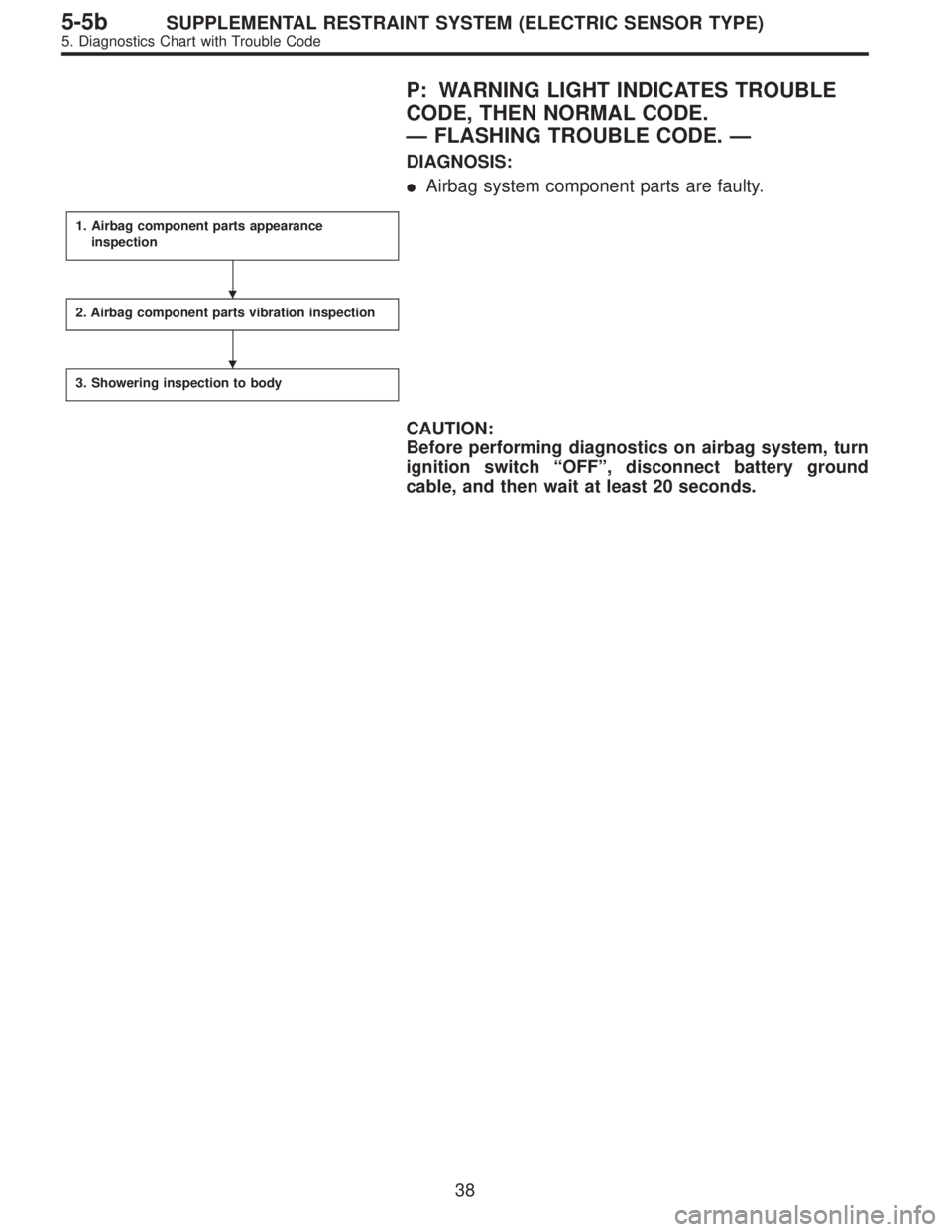
P: WARNING LIGHT INDICATES TROUBLE
CODE, THEN NORMAL CODE.
—FLASHING TROUBLE CODE.—
DIAGNOSIS:
�Airbag system component parts are faulty.
1. Airbag component parts appearance
inspection
2. Airbag component parts vibration inspection
3. Showering inspection to body
CAUTION:
Before performing diagnostics on airbag system, turn
ignition switch“OFF”, disconnect battery ground
cable, and then wait at least 20 seconds.
�
�
38
5-5bSUPPLEMENTAL RESTRAINT SYSTEM (ELECTRIC SENSOR TYPE)
5. Diagnostics Chart with Trouble Code
Page 2695 of 2890

Q: WARNING LIGHT INDICATES TROUBLE
CODE, THEN NORMAL CODE.
—FLASHING NORMAL CODE.—
DIAGNOSIS:
�Airbag connector is faulty.
�Fuse No. 16 is blown.
�Airbag main harness is faulty.
�Airbag control module is faulty.
�Body harness is faulty.
1. Airbag connector appearance inspection
2. Airbag connector vibration inspection
3. Showering inspection to body
4. Fuse No. 16, airbag main harness, airbag
control module, body harness appearance
inspection
5. Fuse No. 16, airbag main harness, body
harness vibration inspection
6. Showering inspection to body
7. Warning light illumination check
CAUTION:
Before performing diagnostics on airbag system, turn
ignition switch“OFF”, disconnect battery ground
cable, and then wait at least 20 seconds.
1. AIRBAG CONNECTOR APPEARANCE INSPECTION
Conduct appearance inspection on airbag connectors
(AB2) through (AB8).
: Is there anything unusual about the appear-
ance of connectors (AB2) through (AB8)?
: Replace faulty airbag component parts.
: Go to step2.
NOTE:
Check terminals, case and wiring harnesses for damage.
�
�
�
�
�
�
41
5-5bSUPPLEMENTAL RESTRAINT SYSTEM (ELECTRIC SENSOR TYPE)
5. Diagnostics Chart with Trouble Code
Page 2697 of 2890

5. FUSE No. 16, AIRBAG MAIN HARNESS, BODY
HARNESS VIBRATION INSPECTION
Conduct vibration inspection on fuse No. 16, airbag main
harness and body harness.
CAUTION:
Do not shake or vibrate airbag control module.
: Do fuse No. 16, airbag main harness or
body harness malfunction again when shak-
ing?
: Replace faulty airbag component parts.
: Go to step6.
NOTE:
Gently shake each part.
G5M0461
6. SHOWERING INSPECTION TO BODY
Spray water on vehicle body.
CAUTION:
Do not directly spray water on each part.
: Does water leak into the passenger com-
partment when showering vehicle?
: Replace faulty airbag component parts.
: Go to step7.
NOTE:
If leaks are noted, check wiring harnesses as water may
leak along them and get parts wet.
7. WARNING LIGHT ILLUMINATION CHECK
Turn ignition switch“ON”(engine off) and observe airbag
warning light.
: Does the airbag warning light comes on for
8 seconds, then go out and stay out?
: Clear memory.
: Go to 5-5b [T4E0]“DIAGNOSTICS PROCE-
DURE”.
43
5-5bSUPPLEMENTAL RESTRAINT SYSTEM (ELECTRIC SENSOR TYPE)
5. Diagnostics Chart with Trouble Code
Page 2750 of 2890

MB-2 Power window circuit breaker
MB-3Engine control module
Fuel pump relay
Main relay
OBD-II service connector
MB-4 A/C relay holder
MB-5 He")
No. Load
MB-1Fuse holder (Rear power supply & seat
heater)
MB-2 Power window circuit breaker
MB-3Engine control module
Fuel pump relay
Main relay
OBD-II service connector
MB-4 A/C relay holder
MB-5 Headlight alarm relay (with security)
MB-6 Headlight LH
MB-7Daytime running light control module
Diode (Lighting)
Diode (Security)
Lighting switch
MB-8Combination meter
Front fog light switch
Headlight RH
Front fog light relay
MB-9Door lock timer
Headlight alarm relay
Interrupt relay
Radio
Security control module
Security indicator light
Spot light
Room light
Step light
Combination meter
Luggage room light
Trailer connector
Trunk room light
MB-10 A/C relay holder
SBF-6ABS relay box
TCS motor relay
SBF-7 TCS valve relay
ALT-1Combination meter
Daytime running light control module
Diode (TCS)
IG Headlight alarm relay
STCruise control module
Engine control module
Inhibitor switch (AT)
Interrupt relay
Starter interlock relay (MT)
FB-1Front washer motor
Rear washer motor
FB-2 Diode (A/C)
FB-3A/C relay holder
Sub fan motor
FB-4Engine control module
Fuel pump relay
Ignition coil
Transmission control module
FB-5 ABS relay boxNo. Load
FB-6Side marker light LH
Side marker light RH
FB-7 Door lock timer
FB-9 Hazard switch
FB-10AT shift lock control module
Key warning switch
Power antenna
FB-11 Radio
FB-12 Cigarette lighter socket
FB-13Mirror heater
Rear power supply relay
Remote control rearview mirror switch
Security control module
Vanity mirror illumination light
FB-14AT shift lock control module
Combination switch
Front wiper motor
Rear wiper motor
Rear wiper relay
FB-15ABS/TCS control module
Transmission control module
FB-16Rear defogger
Rear defogger condenser
Rear defogger switch
FB-17 Rear defogger switch
FB-18AT shift lock control module
Back-up light switch (MT)
Inhibitor switch (AT)
FB-19 Hazard switch
FB-20A/C switch
Combination meter
Mode control panel
TCS off switch
FB-21 Combination meter (Airbag)
FB-22Blower motor relay
Check connector
Daytime running light control module
Daytime running light relay
FRESH/RECIRC actuator
Hi-beam relay
Power window and sunroof relay
Seat belt timer
FB-23 Airbag control module
20
6-3WIRING DIAGRAM
6. Wiring Diagram