Page 2362 of 2890
B4M0798A
B4M0811A
7B8
CHECK VALVE RELAY.
1) Measure resistance between valve relay terminal and
terminal.
: Terminals
No. 30—No. 87:
Is resistance more than 1 MΩ?
No. 30—No. 87a:
Is resistance less than 0.5Ω?
: Go to next step.
: Replace valve relay.
2) Connect battery to valve relay terminal No. 85 and No.
86.
3) Measure resistance between valve relay terminals.
: Terminals
No. 30—No. 87:
Is resistance less than 0.5Ω?
No. 30—No. 87a:
Is resistance more than 1 MΩ?
: Go to step7B9.
: Replace valve relay.
7B9
CHECK HYDRAULIC CONTROL UNIT.
1) Turn ignition switch to OFF.
2) Connect connector (ABS1) to hydraulic control unit.
3) Turn ignition switch to ON.
: Is the ABS warning light off?
: Go to step7B10.
: Replace hydraulic control unit and check fuse No.
19.
22
4-4cBRAKES [ABS 5.3 TYPE]
7. Diagnostics Chart for ABS Warning Light Circuit and Diagnosis Circuit Failure
Page 2363 of 2890
B4M0800A
7B10
CHECK DIAGNOSIS TERMINAL.
Measure resistance between diagnosis terminals (B81)
and chassis ground.
: Terminals
Diagnosis terminal (A)—Chassis ground:
Diagnosis terminal (B)—Chassis ground:
Is the resistance less than 1Ω?
: Go to step7B11.
: Repair diagnosis terminal harness.
B4M0801A
7B11
CHECK DIAGNOSIS LINE.
1) Turn ignition switch to OFF.
2) Connect diagnosis terminal to diagnosis connector
(B82) No. 6.
3) Disconnect connector from ABSCM.
4) Measure resistance between ABSCM connector and
chassis ground.
: Connector & terminal
(F49) No. 13—Chassis ground:
Is the resistance less than 1Ω?
: Go to step7B12.
: Repair harness connector between ABSCM and
diagnosis connector.
7B12CHECK POOR CONTACT IN ABSCM
CONNECTOR.
: Is there poor contact in ABSCM connector?
: Repair connector.
: Replace ABSCM.
23
4-4cBRAKES [ABS 5.3 TYPE]
7. Diagnostics Chart for ABS Warning Light Circuit and Diagnosis Circuit Failure
Page 2364 of 2890
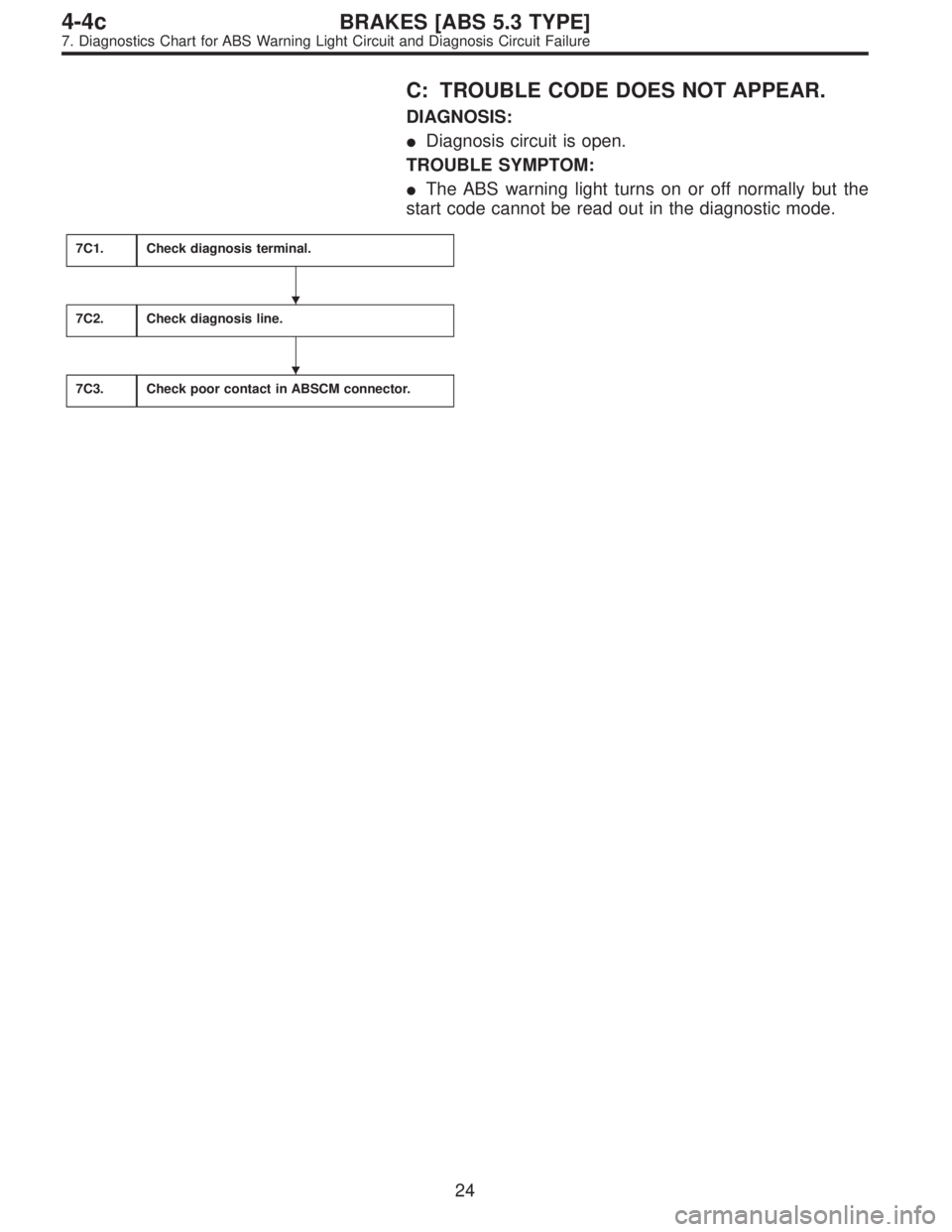
C: TROUBLE CODE DOES NOT APPEAR.
DIAGNOSIS:
�Diagnosis circuit is open.
TROUBLE SYMPTOM:
�The ABS warning light turns on or off normally but the
start code cannot be read out in the diagnostic mode.
7C1.Check diagnosis terminal.
7C2.Check diagnosis line.
7C3.Check poor contact in ABSCM connector.
�
�
24
4-4cBRAKES [ABS 5.3 TYPE]
7. Diagnostics Chart for ABS Warning Light Circuit and Diagnosis Circuit Failure
Page 2365 of 2890
WIRING DIAGRAM:
B4M1034
B4M0800A
7C1
CHECK DIAGNOSIS TERMINAL.
Measure resistance between diagnosis terminals (B81)
and chassis ground.
: Terminals
Diagnosis terminal (A)—Chassis ground:
Diagnosis terminal (B)—Chassis ground:
Is the resistance less than 0.5Ω?
: Go to step7C2.
: Repair diagnosis terminal harness.
25
4-4cBRAKES [ABS 5.3 TYPE]
7. Diagnostics Chart for ABS Warning Light Circuit and Diagnosis Circuit Failure
Page 2366 of 2890
B4M0801A
7C2
CHECK DIAGNOSIS LINE.
1) Turn ignition switch to OFF.
2) Connect diagnosis terminal to diagnosis connector
(B82) No. 6.
3) Disconnect connector from ABSCM.
4) Measure resistance between ABSCM connector and
chassis ground.
: Connector & terminal
(F49) No. 13—Chassis ground:
Is the resistance less than 0.5Ω?
: Go to step7C3.
: Repair harness connector between ABSCM and
diagnosis connector.
7C3CHECK POOR CONTACT IN ABSCM
CONNECTOR.
: Is there poor contact in ABSCM connector?
: Repair connector.
: Replace ABSCM.
26
4-4cBRAKES [ABS 5.3 TYPE]
7. Diagnostics Chart for ABS Warning Light Circuit and Diagnosis Circuit Failure
Page 2452 of 2890

Function code
Measuring items Contents to be monitored Scroll Ref. to
Code Abbreviation
FA 0B1 Stop light switchLED 1 comes on with the switch on (with the brak")
2. FA MODE (ON/OFF DATA ARE DISPLAYED.)
Function code
Measuring items Contents to be monitored Scroll Ref. to
Code Abbreviation
FA 0B1 Stop light switchLED 1 comes on with the switch on (with the brake
pedal down).
Possible 4-4c [T9I0] VR Valve relay signal LED 2 comes on with the valve relay off.
MR Motor relay signal LED 3 comes on with the motor on.
AT AT ABS signal LED 4 comes on when ABS control is on.
AW ABS warning light LED 6 comes on when the warning light is on.
VM Valve relay monitor LED 1 comes on with the valve relay off.
MM Motor relay monitor LED 8 comes on when the motor relay is on.
CM CCM signal LED 9 comes on when ABS control is on.
3. FB MODE (TROUBLE CODES ARE DISPLAYED.)
Function code
Measuring items Contents to be monitored Scroll Ref. to
Code Abbreviation
FB1D⋅ALL
History of trouble
codes is displayed.A maximum of 3 trouble codes are displayed in order
of occurrence.
Possible 4-4c [T10B0] D⋅NEWThe most recent trouble code appears on the select
monitor display.
D⋅MIDThe second most recent trouble code appears on the
select monitor display.
D⋅OLDThe third most recent trouble code appears on the
select monitor display.
B4M0919
NOTE:
�If a particular trouble code is not properly stored in
memory (due to a drop in ABSCM power supply, etc.) when
a problem occurs, the trouble code, followed by a question
mark“?”, appears on the select monitor display. This shows
it may be an unreliable reading.
�*a* refers to the troubles in order of occurrence (NEW.
MID and OLD).
11 2
4-4cBRAKES [ABS 5.3 TYPE]
9. Select Monitor Function Mode
Page 2458 of 2890
LED No. Signal name Display
1 Stop light switch B1
2 Valve relay signal VR
3 Motor relay signal MR
4 AT ABS signal AT
5——
6 ABS warning light AW
7 Valve relay monitor VM
8 Motor relay monitor MM
9 CCM signal CM
10——
B1 VR MR AT—
AW VM MM CM—
1
2345
678910
I: MODE FA0
—ON↔OFF SIGNAL—
Requirement for LED“ON”
LED No. 1 Stop light switch is turned ON. (With brake
pedal depressed.)
LED No. 2 Valve relay is turned OFF.
LED No. 3 Motor relay is turned ON.
LED No. 4 ABS control operates.
LED No. 6 ABS warning light is ON.
LED No. 7 Valve relay is turned OFF.
LED No. 8 Motor relay is turned ON.
LED No. 9 ABS control operates.
11 8
4-4cBRAKES [ABS 5.3 TYPE]
9. Select Monitor Function Mode
Page 2463 of 2890
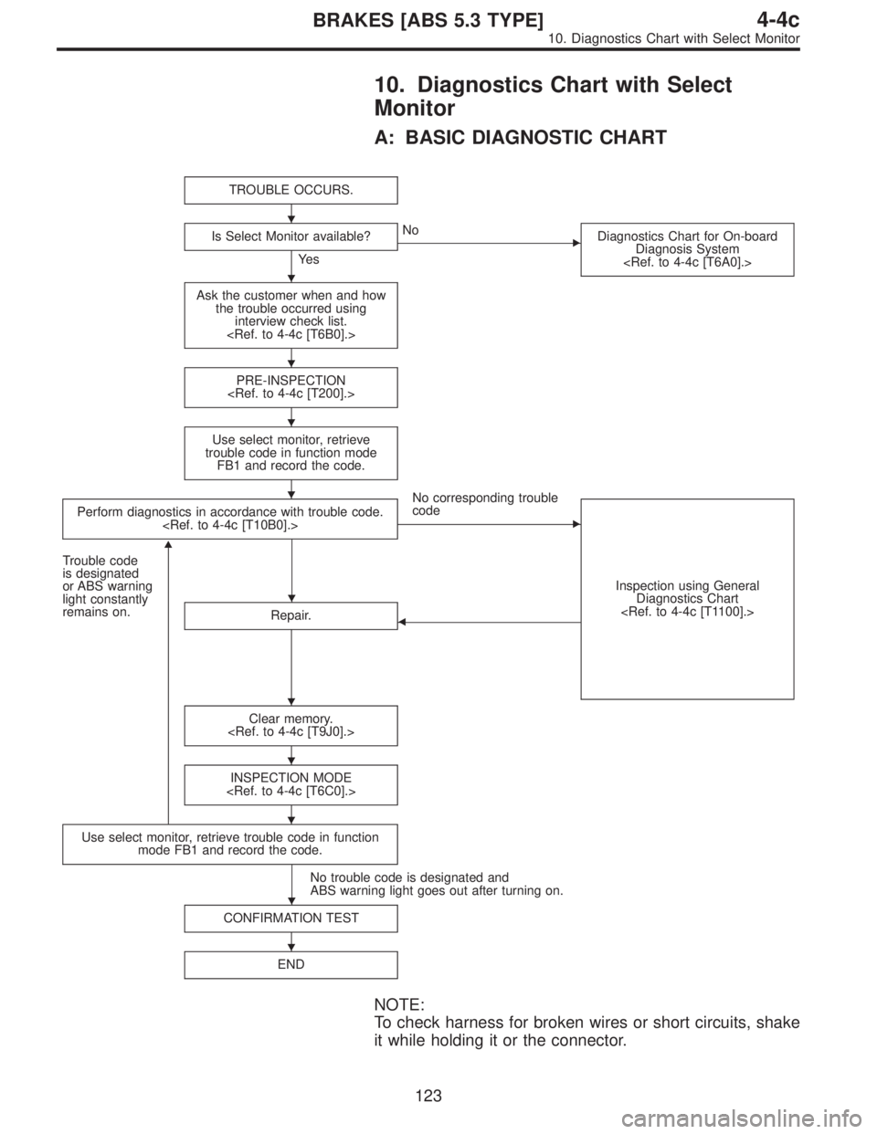
10. Diagnostics Chart with Select
Monitor
A: BASIC DIAGNOSTIC CHART
TROUBLE OCCURS.
Is Select Monitor available?
Ye s
�No
Diagnostics Chart for On-board
Diagnosis System
Ask the customer when and how
the trouble occurred using
interview check list.
PRE-INSPECTION
Use select monitor, retrieve
trouble code in function mode
FB1 and record the code.
Perform diagnostics in accordance with trouble code.
No corresponding trouble
code
�
Inspection using General
Diagnostics Chart
Trouble code
is designated
or ABS warning
light constantly
remains on.
�
Repair.�
Clear memory.
INSPECTION MODE
Use select monitor, retrieve trouble code in function
mode FB1 and record the code.
No trouble code is designated and
ABS warning light goes out after turning on.
CONFIRMATION TEST
END
NOTE:
To check harness for broken wires or short circuits, shake
it while holding it or the connector.
�
�
�
�
�
�
�
�
�
�
�
123
4-4cBRAKES [ABS 5.3 TYPE]
10. Diagnostics Chart with Select Monitor
 Measure resistance between valve relay terminal and
terminal.
: Terminals
No. 30—No. 87:
Is resistance more than 1 MΩ?
No. 30—No. 87a:
Is resistance l")

and chassis ground.
: Terminals
Diagnosis terminal (A)—Chassis ground:
Diagnosis terminal (B)—Chassis g")

and chassis ground.
: Terminals
Diagnosis terminal (A)—Chassis ground:
Diagnosis t")
 Turn ignition switch to OFF.
2) Connect diagnosis terminal to diagnosis connector
(B82) No. 6.
3) Disconnect connector from ABSCM.
4) Measure resistance between A")