Page 1156 of 2890
![SUBARU LEGACY 1996 Service Repair Manual 6. Control Valve (Power Steering
Gearbox) [RHD model]
NOTE:
This section focuses on the disassembly and reassembly
of control valve. For the inspection and adjustment and the
service procedures for as SUBARU LEGACY 1996 Service Repair Manual 6. Control Valve (Power Steering
Gearbox) [RHD model]
NOTE:
This section focuses on the disassembly and reassembly
of control valve. For the inspection and adjustment and the
service procedures for as](/manual-img/17/57433/w960_57433-1155.png)
6. Control Valve (Power Steering
Gearbox) [RHD model]
NOTE:
This section focuses on the disassembly and reassembly
of control valve. For the inspection and adjustment and the
service procedures for associated parts, refer to“Steering
Gearbox”.
B4M0668A
A: CHECKING OIL LEAKING POINTS
1. OIL LEAKING POINTS
1) If leak point is other than a, b, c, or d, perform check
step 5) in 4-3 [W6A2] before dismounting gearbox from
vehicle. If gearbox is dismounted without confirming where
the leak is, it must be mounted again to locate the leak
point.
2) Even if the location of the leak can be easily found by
observing the leaking condition, it is necessary to thor-
oughly remove the oil from the suspected portion and turn
the steering wheel from lock to lock about 30 to 40 times
with engine running, then make comparison of the sus-
pected portion between immediately after and several
hours after this operation.
3) Before starting oil leak repair work, be sure to clean the
gearbox, hoses, pipes, and surrounding parts. After com-
pleting repair work, clean these areas again.
49
4-3SERVICE PROCEDURE
6. Control Valve (Power Steering Gearbox) [RHD model]
Page 1157 of 2890
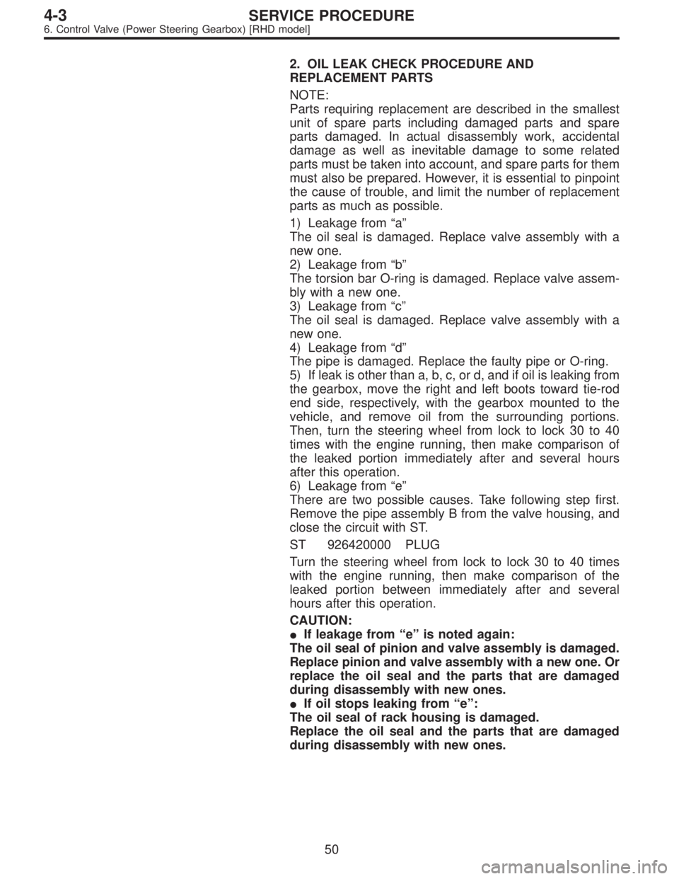
2. OIL LEAK CHECK PROCEDURE AND
REPLACEMENT PARTS
NOTE:
Parts requiring replacement are described in the smallest
unit of spare parts including damaged parts and spare
parts damaged. In actual disassembly work, accidental
damage as well as inevitable damage to some related
parts must be taken into account, and spare parts for them
must also be prepared. However, it is essential to pinpoint
the cause of trouble, and limit the number of replacement
parts as much as possible.
1) Leakage from“a”
The oil seal is damaged. Replace valve assembly with a
new one.
2) Leakage from“b”
The torsion bar O-ring is damaged. Replace valve assem-
bly with a new one.
3) Leakage from“c”
The oil seal is damaged. Replace valve assembly with a
new one.
4) Leakage from“d”
The pipe is damaged. Replace the faulty pipe or O-ring.
5) If leak is other than a, b, c, or d, and if oil is leaking from
the gearbox, move the right and left boots toward tie-rod
end side, respectively, with the gearbox mounted to the
vehicle, and remove oil from the surrounding portions.
Then, turn the steering wheel from lock to lock 30 to 40
times with the engine running, then make comparison of
the leaked portion immediately after and several hours
after this operation.
6) Leakage from“e”
There are two possible causes. Take following step first.
Remove the pipe assembly B from the valve housing, and
close the circuit with ST.
ST 926420000 PLUG
Turn the steering wheel from lock to lock 30 to 40 times
with the engine running, then make comparison of the
leaked portion between immediately after and several
hours after this operation.
CAUTION:
�If leakage from“e”is noted again:
The oil seal of pinion and valve assembly is damaged.
Replace pinion and valve assembly with a new one. Or
replace the oil seal and the parts that are damaged
during disassembly with new ones.
�If oil stops leaking from“e”:
The oil seal of rack housing is damaged.
Replace the oil seal and the parts that are damaged
during disassembly with new ones.
50
4-3SERVICE PROCEDURE
6. Control Valve (Power Steering Gearbox) [RHD model]
Page 1159 of 2890
G4M0821
2) Install ST on valve side of rack and press outer side oil
seal out.
ST 34099FA030 INSTALLER & REMOVER
CAUTION:
�Block pipe connection of steering body to prevent
fluid from flowing out.
�Do not allow rack to come in contact with inner wall
of cylinder. Otherwise, cylinder wall may be scratched,
resulting in oil leaks.
�Remove holder and rack as a unit.
�Check rack and steering body for bends or cracks
and replace as required.
�Discard oil seal after removal and replace with new
ones.
G4M0822
3) Insert ST from valve side and press back-up ring and oil
seal out.
CAUTION:
Discard back-up ring and oil seal after removal and
replace with new ones.
ST 927580000 REMOVER
52
4-3SERVICE PROCEDURE
6. Control Valve (Power Steering Gearbox) [RHD model]
Page 1160 of 2890
G4M0823
4) Using ST1 and ST2, repair cylinder’s clinched sections.
ST1 34099FA080 PUNCH
ST2 34099FA070 BASE
G4M0889
5) If cylinder edge is deformed in a convex shape, repair
using an oil stone.
G4M0824
C: REPLACEMENT OF SEAL AND PACKING
1. VALVE HOUSING OIL SEAL
�Removal
1) After removing dust cover, extract pinion and valve from
valve housing.
CAUTION:
�If pinion and valve is difficult to remove, use a press.
�Discard Y-packing after removal and replace with a
new one.
�Check rotor for bends and serrations for damage
and replace as required.
53
4-3SERVICE PROCEDURE
6. Control Valve (Power Steering Gearbox) [RHD model]
Page 1170 of 2890
G4M0101
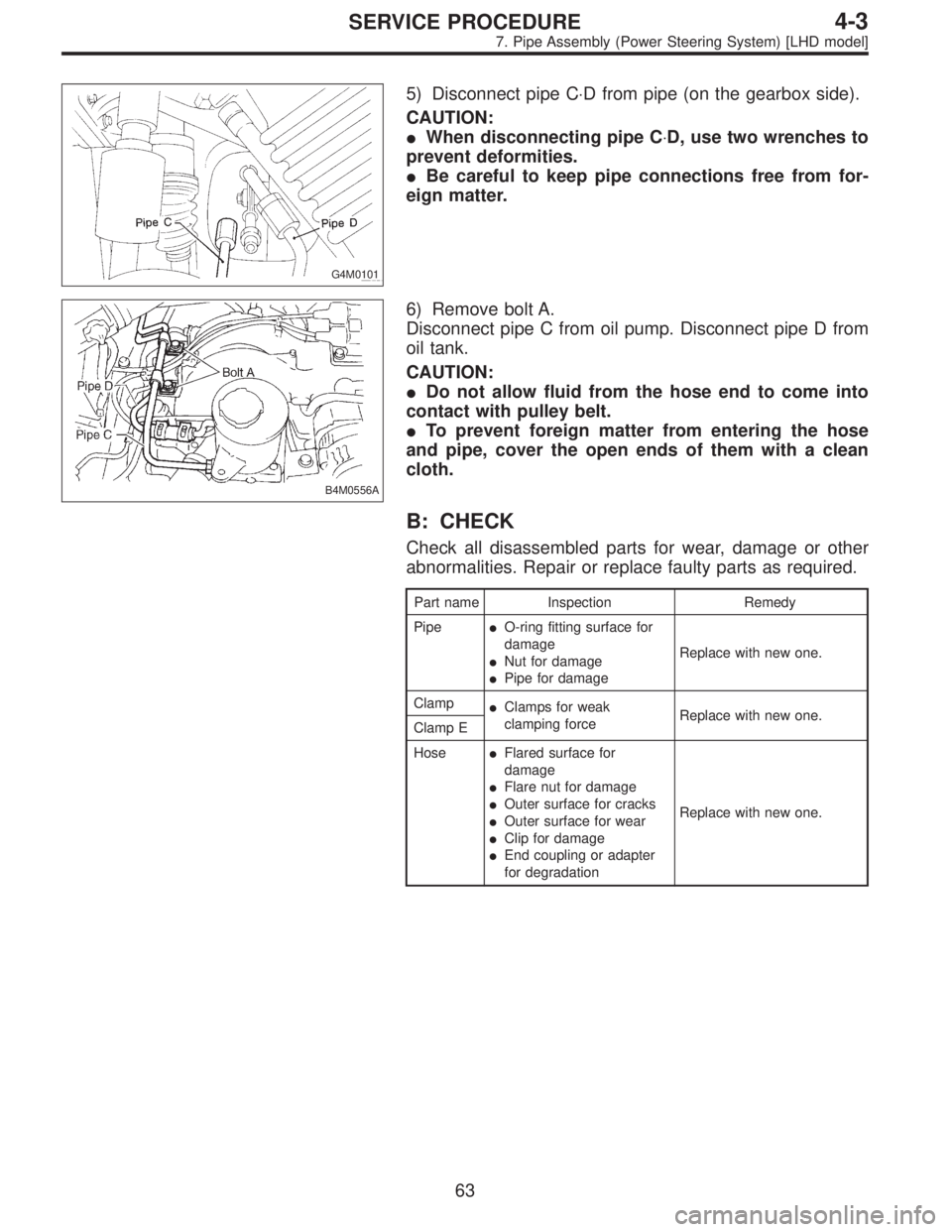
5) Disconnect pipe C⋅D from pipe (on the gearbox side).
CAUTION:
�When disconnecting pipe C⋅D, use two wrenches to
prevent deformities.
�Be careful to keep pipe connections free from for-
eign matter.
B4M0556A
6) Remove bolt A.
Disconnect pipe C from oil pump. Disconnect pipe D from
oil tank.
CAUTION:
�Do not allow fluid from the hose end to come into
contact with pulley belt.
�To prevent foreign matter from entering the hose
and pipe, cover the open ends of them with a clean
cloth.
B: CHECK
Check all disassembled parts for wear, damage or other
abnormalities. Repair or replace faulty parts as required.
Part name Inspection Remedy
Pipe�O-ring fitting surface for
damage
�Nut for damage
�Pipe for damageReplace with new one.
Clamp
�Clamps for weak
clamping forceReplace with new one.
Clamp E
Hose�Flared surface for
damage
�Flare nut for damage
�Outer surface for cracks
�Outer surface for wear
�Clip for damage
�End coupling or adapter
for degradationReplace with new one.
63
4-3SERVICE PROCEDURE
7. Pipe Assembly (Power Steering System) [LHD model]
Page 1175 of 2890
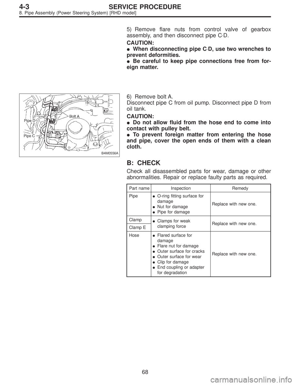
5) Remove flare nuts from control valve of gearbox
assembly, and then disconnect pipe C⋅D.
CAUTION:
�When disconnecting pipe C⋅D, use two wrenches to
prevent deformities.
�Be careful to keep pipe connections free from for-
eign matter.
B4M0556A
6) Remove bolt A.
Disconnect pipe C from oil pump. Disconnect pipe D from
oil tank.
CAUTION:
�Do not allow fluid from the hose end to come into
contact with pulley belt.
�To prevent foreign matter from entering the hose
and pipe, cover the open ends of them with a clean
cloth.
B: CHECK
Check all disassembled parts for wear, damage or other
abnormalities. Repair or replace faulty parts as required.
Part name Inspection Remedy
Pipe�O-ring fitting surface for
damage
�Nut for damage
�Pipe for damageReplace with new one.
Clamp
�Clamps for weak
clamping forceReplace with new one.
Clamp E
Hose�Flared surface for
damage
�Flare nut for damage
�Outer surface for cracks
�Outer surface for wear
�Clip for damage
�End coupling or adapter
for degradationReplace with new one.
68
4-3SERVICE PROCEDURE
8. Pipe Assembly (Power Steering System) [RHD model]
Page 1179 of 2890
B4M0561A
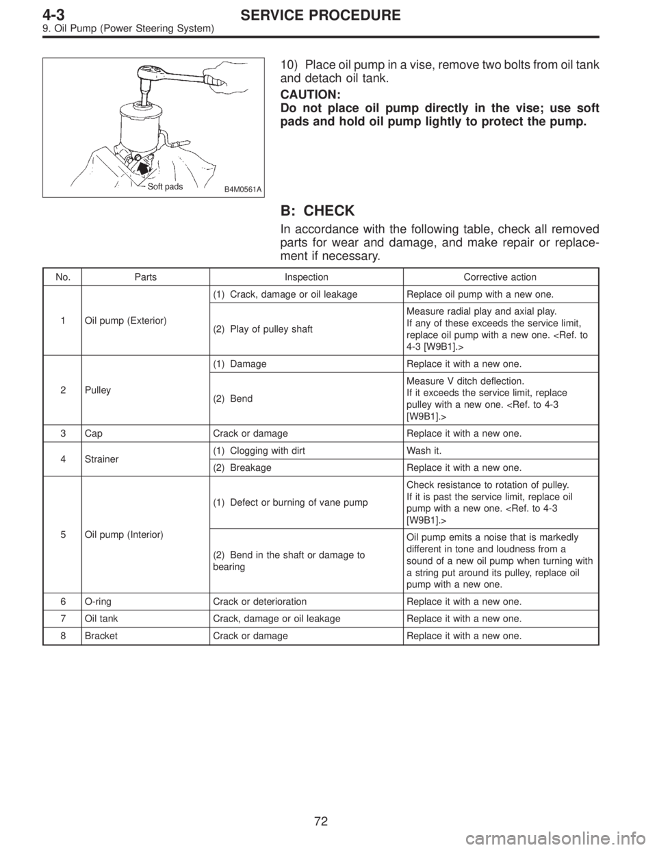
10) Place oil pump in a vise, remove two bolts from oil tank
and detach oil tank.
CAUTION:
Do not place oil pump directly in the vise; use soft
pads and hold oil pump lightly to protect the pump.
B: CHECK
In accordance with the following table, check all removed
parts for wear and damage, and make repair or replace-
ment if necessary.
No. Parts Inspection Corrective action
1 Oil pump (Exterior)(1) Crack, damage or oil leakage Replace oil pump with a new one.
(2) Play of pulley shaftMeasure radial play and axial play.
If any of these exceeds the service limit,
replace oil pump with a new one.
4-3 [W9B1].>
2 Pulley(1) Damage Replace it with a new one.
(2) BendMeasure V ditch deflection.
If it exceeds the service limit, replace
pulley with a new one.
[W9B1].>
3 Cap Crack or damage Replace it with a new one.
4 Strainer(1) Clogging with dirt Wash it.
(2) Breakage Replace it with a new one.
5 Oil pump (Interior)(1) Defect or burning of vane pumpCheck resistance to rotation of pulley.
If it is past the service limit, replace oil
pump with a new one.
[W9B1].>
(2) Bend in the shaft or damage to
bearingOil pump emits a noise that is markedly
different in tone and loudness from a
sound of a new oil pump when turning with
a string put around its pulley, replace oil
pump with a new one.
6 O-ring Crack or deterioration Replace it with a new one.
7 Oil tank Crack, damage or oil leakage Replace it with a new one.
8 Bracket Crack or damage Replace it with a new one.
72
4-3SERVICE PROCEDURE
9. Oil Pump (Power Steering System)
Page 1186 of 2890
6) Check
(1) When reassembly procedures have been
completed, turn shaft by hand to ensure it turns
smoothly. If it binds or other unusual conditions are
evident, disassemble again and check for foreign mat-
ter trapped on sliding surfaces and improper installa-
tion. Eliminate the cause of trouble.
(2) Check followings by referring to“CHECK”article.
�Excessive play in pulley shaft
�Ditch deflection of pulley
�Resistance to rotation of pulley
�Measurement of generated oil pressure
F: INSTALLATION
1) Install bracket on engine.
Tightening torque:
22±2 N⋅m (2.2±0.2 kg-m, 15.9±1.4 ft-lb)
2) Install oil pump on oil tank as follows outside the
vehicle:
NOTE:
Prior to installation, make sure that all oil is removed from
oil pump, oil tank and pipe.
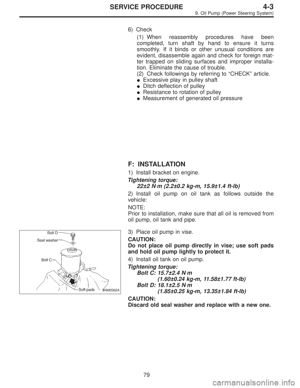
B4M0562A
3) Place oil pump in vise.
CAUTION:
Do not place oil pump directly in vise; use soft pads
and hold oil pump lightly to protect it.
4) Install oil tank on oil pump.
Tightening torque:
Bolt C: 15.7±2.4 N⋅m
(1.60±0.24 kg-m, 11.58±1.77 ft-lb)
Bolt D: 18.1±2.5 N⋅m
(1.85±0.25 kg-m, 13.35±1.84 ft-lb)
CAUTION:
Discard old seal washer and replace with a new one.
79
4-3SERVICE PROCEDURE
9. Oil Pump (Power Steering System)