Page 916 of 2890
G3M0906
5) Temporarily assemble lower valve body to upper valve
body.
CAUTION:
Be careful not to drop the upper body interior steel
ball, or the lower body interior filter, orifice check
spring, or orifice check valve.
B3M0406A
6) Install the duty solenoid B and the four brackets.
7) Tighten twenty seven bolts & washers and two reamer
bolts.
Tightening torque:
T1: 8±1 N⋅m (0.8±0.1 kg-m, 5.8±0.7 ft-lb)
T2: 11.3±1.5 N⋅m (1.15±0.15 kg-m, 8.3±1.1 ft-lb)
Unit: mm (in)
abcde
Length 70 (2.76) 50 (1.97) 33 (1.30) 27 (1.06) 28 (1.10)
Numbers 2 6 16 1 2
G3M0864
8) Install the shift solenoid and duty solenoid A.
a length : 16 mm (0.63 in)
b length : 27 mm (1.06 in)
Tightening torque:
8±1 N⋅m (0.8±0.1 kg-m, 5.8±0.7 ft-lb)
G3M0445
7. Oil Pump Assembly
A: DISASSEMBLY
1) Remove the oil seal retainer.
Also remove the O-ring and oil seal (air breather).
89
3-2SERVICE PROCEDURE
6. Control Valve Body - 7. Oil Pump Assembly
Page 919 of 2890
G3M0454
2) Install the vane ring, rotor and vanes into the housing
in this sequence.
G3M0455
3) Install the return spring and retainer between the hous-
ing and cam ring.
G3M0456
4) Install the control piston to the oil pump housing.
NOTE:
Fit the seal in the piston groove, with the red seals facing
the top side. (Two side seals and one plain seal are
attached.)
5) Set the rotor at the center of the housing bore. Apply
ATF abundantly to each rotary portion.
G3M0446
6) Install the oil pump cover.
Tightening torque:
25±2 N⋅m (2.5±0.2 kg-m, 18.1±1.4 ft-lb)
NOTE:
�Align both pivots with the pivot holes of the cover, and
install the cover being careful not to apply undue force to
the pivots.
�After assembling, turn the oil pump shaft to check for
smooth rotation of the rotor.
G3M0449
NOTE:
�Install the oil seal retainer and seal rings (R) and (H)
after adjusting the drive pinion backlash and tooth contact.
92
3-2SERVICE PROCEDURE
7. Oil Pump Assembly
Page 924 of 2890

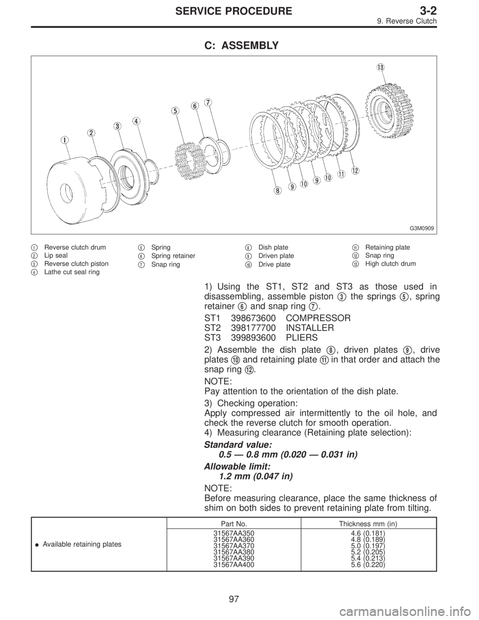
C: ASSEMBLY
G3M0909
�1Reverse clutch drum
�
2Lip seal
�
3Reverse clutch piston
�
4Lathe cut seal ring�
5Spring
�
6Spring retainer
�
7Snap ring�
8Dish plate
�
9Driven plate
�
10Drive plate�
11Retaining plate
�
12Snap ring
�
13High clutch drum
1) Using the ST1, ST2 and ST3 as those used in
disassembling, assemble piston�
3the springs�5, spring
retainer�
6and snap ring�7.
ST1 398673600 COMPRESSOR
ST2 398177700 INSTALLER
ST3 399893600 PLIERS
2) Assemble the dish plate�
8, driven plates�9, drive
plates�
10and retaining plate�11in that order and attach the
snap ring�
12.
NOTE:
Pay attention to the orientation of the dish plate.
3) Checking operation:
Apply compressed air intermittently to the oil hole, and
check the reverse clutch for smooth operation.
4) Measuring clearance (Retaining plate selection):
Standard value:
0.5—0.8 mm (0.020—0.031 in)
Allowable limit:
1.2 mm (0.047 in)
NOTE:
Before measuring clearance, place the same thickness of
shim on both sides to prevent retaining plate from tilting.
�Available retaining platesPart No. Thickness mm (in)
31567AA350
31567AA360
31567AA370
31567AA380
31567AA390
31567AA4004.6 (0.181)
4.8 (0.189)
5.0 (0.197)
5.2 (0.205)
5.4 (0.213)
5.6 (0.220)
97
3-2SERVICE PROCEDURE
9. Reverse Clutch
Page 926 of 2890

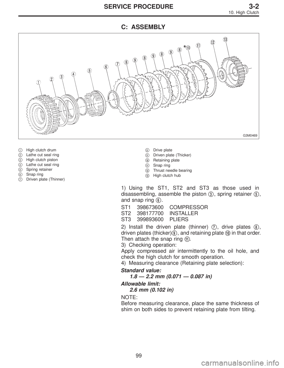
C: ASSEMBLY
G3M0469
�1High clutch drum
�
2Lathe cut seal ring
�
3High clutch piston
�
4Lathe cut seal ring
�
5Spring retainer
�
6Snap ring
�
7Driven plate (Thinner)�
8Drive plate
�
9Driven plate (Thicker)
�
10Retaining plate
�
11Snap ring
�
12Thrust needle bearing
�
13High clutch hub
1) Using the ST1, ST2 and ST3 as those used in
disassembling, assemble the piston�
3, spring retainer�5,
and snap ring�
6.
ST1 398673600 COMPRESSOR
ST2 398177700 INSTALLER
ST3 399893600 PLIERS
2) Install the driven plate (thinner)�
7, drive plates�8,
driven plates (thicker)�
9, and retaining plate�10in that order.
Then attach the snap ring�
11.
3) Checking operation:
Apply compressed air intermittently to the oil hole, and
check the high clutch for smooth operation.
4) Measuring clearance (Retaining plate selection):
Standard value:
1.8—2.2 mm (0.071—0.087 in)
Allowable limit:
2.6 mm (0.102 in)
NOTE:
Before measuring clearance, place the same thickness of
shim on both sides to prevent retaining plate from tilting.
99
3-2SERVICE PROCEDURE
10. High Clutch
Page 971 of 2890
G3M0031
5) Lightly tap the head of front propeller shaft with a cop-
per hammer until center bearing is removed.
CAUTION:
Be careful not to damage the thread portion.
D: INSPECTION
NOTE:
Do not disassemble propeller shaft. Check the following
and replace if necessary.
1) Tube surfaces for dents or cracks
2) Splines for deformation or abnormal wear
3) Joints for non-smooth operation or abnormal noise
4) Center bearing for free play, noise or non-smooth
operation
5) Oil seals for abnormal wear or damage
6) Center bearing for breakage
G3M0030
E: ASSEMBLY
1) Install center bearing onto front propeller shaft.
2) Align marks and install companion flange.
G3M0029
3) Tighten stake nut until center bearing is set in position.
CAUTION:
Be sure to install new stake nut.
Tightening torque:
270±25 N⋅m (27.5±2.5 kg-m, 199±18 ft-lb)
NOTE:
Stake the nut after tightening.
12
3-4SERVICE PROCEDURE
1. Propeller Shaft
Page 986 of 2890

E: ASSEMBLY
1) Precautions for assembling
(1) Assemble in the reverse order of disassembling.
(2) Check and adjust each part during assembly.
(3) Keep the shims and washers in order, so that they
are not misinstalled.
(4) Thoroughly clean the surfaces on which the shims,
washers and bearings are to be installed.
(5) Apply gear oil when installing the bearings and
thrust washers.
(6) Be careful not to mix up the right and left hand cups
of the bearings.
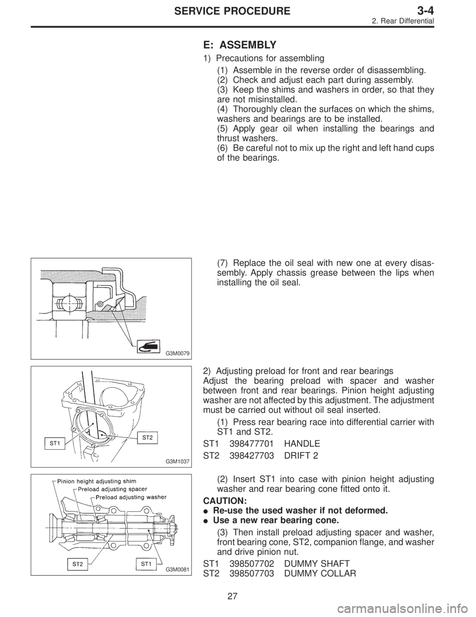
G3M0079
(7) Replace the oil seal with new one at every disas-
sembly. Apply chassis grease between the lips when
installing the oil seal.
G3M1037
2) Adjusting preload for front and rear bearings
Adjust the bearing preload with spacer and washer
between front and rear bearings. Pinion height adjusting
washer are not affected by this adjustment. The adjustment
must be carried out without oil seal inserted.
(1) Press rear bearing race into differential carrier with
ST1 and ST2.
ST1 398477701 HANDLE
ST2 398427703 DRIFT 2
G3M0081
(2) Insert ST1 into case with pinion height adjusting
washer and rear bearing cone fitted onto it.
CAUTION:
�Re-use the used washer if not deformed.
�Use a new rear bearing cone.
(3) Then install preload adjusting spacer and washer,
front bearing cone, ST2, companion flange, and washer
and drive pinion nut.
ST1 398507702 DUMMY SHAFT
ST2 398507703 DUMMY COLLAR
27
3-4SERVICE PROCEDURE
2. Rear Differential
Page 999 of 2890

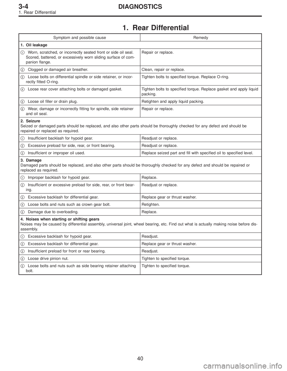
1. Rear Differential
Symptom and possible cause Remedy
1. Oil leakage
�
1Worn, scratched, or incorrectly seated front or side oil seal.
Scored, battered, or excessively worn sliding surface of com-
panion flange.Repair or replace.
�
2Clogged or damaged air breather. Clean, repair or replace.
�
3Loose bolts on differential spindle or side retainer, or incor-
rectly fitted O-ring.Tighten bolts to specified torque. Replace O-ring.
�
4Loose rear cover attaching bolts or damaged gasket. Tighten bolts to specified torque. Replace gasket and apply liquid
packing.
�
5Loose oil filler or drain plug. Retighten and apply liquid packing.
�
6Wear, damage or incorrectly fitting for spindle, side retainer
and oil seal.Repair or replace.
2. Seizure
Seized or damaged parts should be replaced, and also other parts should be thoroughly checked for any defect and should be
repaired or replaced as required.
�
1Insufficient backlash for hypoid gear. Readjust or replace.
�
2Excessive preload for side, rear, or front bearing. Readjust or replace.
�
3Insufficient or improper oil used. Replace seized part and fill with specified oil to specified level.
3. Damage
Damaged parts should be replaced, and also other parts should be thoroughly checked for any defect and should be repaired or
replaced as required.
�
1Improper backlash for hypoid gear. Replace.
�
2Insufficient or excessive preload for side, rear, or front bear-
ing.Readjust or replace.
�
3Excessive backlash for differential gear. Replace gear or thrust washer.
�
4Loose bolts and nuts such as crown gear bolt. Retighten.
�
5Damage due to overloading. Replace.
4. Noises when starting or shifting gears
Noises may be caused by differential assembly, universal joint, wheel bearing, etc. Find out what is actually making noise before dis-
assembly.
�
1Excessive backlash for hypoid gear. Readjust.
�
2Excessive backlash for differential gear. Replace gear or thrust washer.
�
3Insufficient preload for front or rear bearing. Readjust.
�
4Loose drive pinion nut. Tighten to specified torque.
�
5Loose bolts and nuts such as side bearing retainer attaching
bolt.Tighten to specified torque.
40
3-4DIAGNOSTICS
1. Rear Differential
Page 1018 of 2890
G4M0492
3) Remove nut (do not remove bolt.) securing transverse
link to crossmember.
4) Remove two bolts securing bushing bracket of trans-
verse link to vehicle body at rear bushing location.
G4M0493
5) Extract ball joint from housing.
6) Remove bolt securing transverse link to crossmember
and extract transverse link from crossmember.
G4M0494
B: DISASSEMBLY
1. FRONT BUSHING
Using ST, press front bushing out of place.
ST 927680000 INSTALLER & REMOVER SET
G4M0495
2. REAR BUSHING
1) Scribe an aligning mark on transverse link and rear
bushing.
2) Loosen nut and remove rear bushing.
C: INSPECTION
1) Check transverse link for wear, damage and cracks,
and correct or replace if defective.
2) Check bushings for cracks, wear,damage and creeping.
3) Check rear bushing for oil leaks.
4) If defective, replace with new one.
17
4-1SERVICE PROCEDURE
2. Front Transverse Link