Page 1599 of 2890

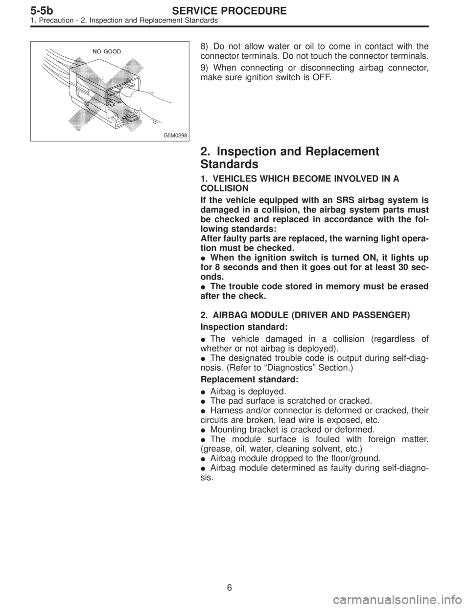
G5M0298
8) Do not allow water or oil to come in contact with the
connector terminals. Do not touch the connector terminals.
9) When connecting or disconnecting airbag connector,
make sure ignition switch is OFF.
2. Inspection and Replacement
Standards
1. VEHICLES WHICH BECOME INVOLVED IN A
COLLISION
If the vehicle equipped with an SRS airbag system is
damaged in a collision, the airbag system parts must
be checked and replaced in accordance with the fol-
lowing standards:
After faulty parts are replaced, the warning light opera-
tion must be checked.
�When the ignition switch is turned ON, it lights up
for 8 seconds and then it goes out for at least 30 sec-
onds.
�The trouble code stored in memory must be erased
after the check.
2. AIRBAG MODULE (DRIVER AND PASSENGER)
Inspection standard:
�The vehicle damaged in a collision (regardless of
whether or not airbag is deployed).
�The designated trouble code is output during self-diag-
nosis. (Refer to“Diagnostics”Section.)
Replacement standard:
�Airbag is deployed.
�The pad surface is scratched or cracked.
�Harness and/or connector is deformed or cracked, their
circuits are broken, lead wire is exposed, etc.
�Mounting bracket is cracked or deformed.
�The module surface is fouled with foreign matter.
(grease, oil, water, cleaning solvent, etc.)
�Airbag module dropped to the floor/ground.
�Airbag module determined as faulty during self-diagno-
sis.
6
5-5bSERVICE PROCEDURE
1. Precaution - 2. Inspection and Replacement Standards
Page 1603 of 2890

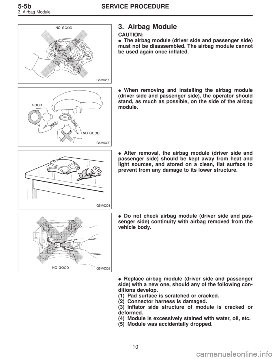
G5M0299
3. Airbag Module
CAUTION:
�The airbag module (driver side and passenger side)
must not be disassembled. The airbag module cannot
be used again once inflated.
G5M0300
�When removing and installing the airbag module
(driver side and passenger side), the operator should
stand, as much as possible, on the side of the airbag
module.
G5M0301
�After removal, the airbag module (driver side and
passenger side) should be kept away from heat and
light sources, and stored on a clean, flat surface to
prevent from any damage to its lower structure.
G5M0302
�Do not check airbag module (driver side and pas-
senger side) continuity with airbag removed from the
vehicle body.
�Replace airbag module (driver side and passenger
side) with a new one, should any of the following con-
ditions develop.
(1) Pad surface is scratched or cracked.
(2) Connector harness is damaged.
(3) Inflator side structure of module is cracked or
deformed.
(4) Module is excessively stained with water, oil, etc.
(5) Module was accidentally dropped.
10
5-5bSERVICE PROCEDURE
3. Airbag Module
Page 1624 of 2890
B6M0431A
11) Take out steel ball from clutch.
CAUTION:
Be careful not to lose steel ball.
B6M0432A
12) Remove idle gear from housing.
B6M0433A
13) Remove retainer and roller from housing.
CAUTION:
Be careful not to drop retainer and roller.
B6M0434A
14) Remove coil spring from magnetic switch.
D: INSPECTION
1. ARMATURE
1) Check commutator for any sign of burns of rough sur-
faces or stepped wear. If wear is of a minor nature, correct
it by using sand paper.
11
6-1SERVICE PROCEDURE
1. Starter
Page 1633 of 2890
B6M0486
5) Ball bearing
Check rear ball bearing. Replace it if it is noisy or if rotor
does not turn smoothly.
G6M0078
2. STATOR
1) Continuity test
Inspect stator coil for continuity between its terminals.
When there is no continuity between individual terminals,
cable is broken.
Replace stator coil.
G6M0079
2) Insulation test
Inspect stator coil for continuity between stator core and
each terminal. If there is continuity, replace stator coil.
B6M0487A
3. BRUSH
Measure brush length. If brush is worn, replace brush
holder assembly.
Brush length (�):
Standard
20.5 mm (0.807 in)
Limit
1.5 mm (0.059 in)
B6M0488A
4. DIODE ASSEMBLY
The diode consists of eight diodes, four each being located
on the positive and negative sides. The diode is necessary
to restrict current flow to one direction.
Check all diodes, for continuity. If any diode is faulty,
replace diode assembly.
19
6-1SERVICE PROCEDURE
2. Generator
Page 1635 of 2890
2) Check operation as shown in chart below.
No.Switch operation
Value of
voltage meterLamp operation
Remarks
123 12
1 ON OFF OFF 12 V DIM ONCheck initial
excitation.
2 ON ON OFF 12 VON
or
BLINKOFF Check total excitation.
3 ON ON OFF 16 VOFF
or
DIM-BLINKOFFWhen value of voltage
meter is between 12
V and 16 V.
4 OFF ON OFF 12 VON
or
BLINKONCheck connection for
S and B terminals.
5 OFF ON ON 18 V ON ONCheck for over
loading of voltage.
G6M0077
D: ASSEMBLY
Assembly is in the reverse order of disassembly proce-
dures.
CAUTION:
�When disassembling generator, replace rear ball
bearing.
�When soldering starter coil to diode, do not touch
lead wire with solder for more than 5 seconds.
B6M0492
�Before installing rear cover, insert pin from outside
of rear cover so that holds brush. After installing rear
cover, remove pin.
B6M0476A
�When installing rear cover, heat portion�Ato 50°C
(122°F) with heater drier.
21
6-1SERVICE PROCEDURE
2. Generator
Page 1636 of 2890

3. Spark Plug
A: REMOVAL AND INSTALLATION
CAUTION:
All spark plugs installed on an engine, must be of the
same heat range.
Spark plug:
CHAMPION: RC10YC4
(Alternate)
NGK: BKR6E-11
NIPPONDENSO: K20PR-U11
1) Remove spark plug cords by pulling boot, not cord itself.
2) Remove spark plugs.
3) When installing spark plugs on cylinder head, use spark
plug wrench.
Tightening torque (Spark plug):
20.6±2.9 N⋅m (2.10±0.30 kg-m, 15.19±2.14 ft-lb)
CAUTION:
The above torque should be only applied to new spark
plugs without oil on their threads.
In case their threads are lubricated, the torque should
be reduced by approximately 1/3 of the specified
torque in order to avoid their over-stressing.
4) Connect spark plug cords.
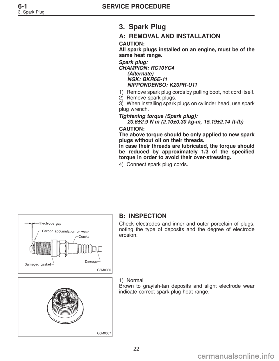
G6M0086
B: INSPECTION
Check electrodes and inner and outer porcelain of plugs,
noting the type of deposits and the degree of electrode
erosion.
G6M0087
1) Normal
Brown to grayish-tan deposits and slight electrode wear
indicate correct spark plug heat range.
22
6-1SERVICE PROCEDURE
3. Spark Plug
Page 1650 of 2890
G6M0093
B: INSPECTION
Using accurate tester, inspect the following items, and
replace if defective.
1) Primary resistance
2) Secondary coil resistance
CAUTION:
If the resistance is extremely low, this indicates the
presence of a short-circuit.
Specified resistance:
[Primary side]
Between�
1and�2
Between�3and�4
0.69Ω±10%
[Secondary side]
Between terminal No. 1 and No. 2
Between terminal No. 2 and No. 3
21.0 kΩ±15%
3) Insulation between primary terminal and case: 10 MΩ
or more.
G6M0094
5. Spark Plug Cord
A: INSPECTION
Check for:
1) Damage to cords, deformation, burning or rust forma-
tion of terminals
2) Resistance values of cords
Resistance value:
5.12—12.34 kΩ
G6M0095
6. Ignitor
A: REMOVAL AND INSTALLATION
1) Disconnect battery ground cable.
B6M0161
2) Disconnect connector from ignitor.
3) Remove screws which hold ignitor onto body.
4) Installation is in the reverse order of removal.
35
6-1SERVICE PROCEDURE
4. Ignition Coil - 6. Ignitor
Page 1651 of 2890
G6M0093
B: INSPECTION
Using accurate tester, inspect the following items, and
replace if defective.
1) Primary resistance
2) Secondary coil resistance
CAUTION:
If the resistance is extremely low, this indicates the
presence of a short-circuit.
Specified resistance:
[Primary side]
Between�
1and�2
Between�3and�4
0.69Ω±10%
[Secondary side]
Between terminal No. 1 and No. 2
Between terminal No. 2 and No. 3
21.0 kΩ±15%
3) Insulation between primary terminal and case: 10 MΩ
or more.
G6M0094
5. Spark Plug Cord
A: INSPECTION
Check for:
1) Damage to cords, deformation, burning or rust forma-
tion of terminals
2) Resistance values of cords
Resistance value:
5.12—12.34 kΩ
G6M0095
6. Ignitor
A: REMOVAL AND INSTALLATION
1) Disconnect battery ground cable.
B6M0161
2) Disconnect connector from ignitor.
3) Remove screws which hold ignitor onto body.
4) Installation is in the reverse order of removal.
35
6-1SERVICE PROCEDURE
4. Ignition Coil - 6. Ignitor