Page 737 of 2890
11) Install front exhaust pipe and center exhaust pipe.
12) Connect hoses, connectors and cables.
(1) Connect the following hoses.
�Fuel delivery hose, return hose and evaporation
hose
�Heater inlet and outlet hoses
�Brake booster vacuum hose
(2) Connect the following connectors.
�Engine ground terminal
�Engine harness connectors
�Front oxygen sensor connector
�Rear oxygen sensor connector
�Alternator connector and terminal
�A/C compressor connectors (With A/C)
(3) Connect the following cables.
�Accelerator cable
�Cruise control cables (With cruise control)
�Clutch cable
�Clutch release spring
CAUTION:
After connecting each cable, adjust them.
G2M0271
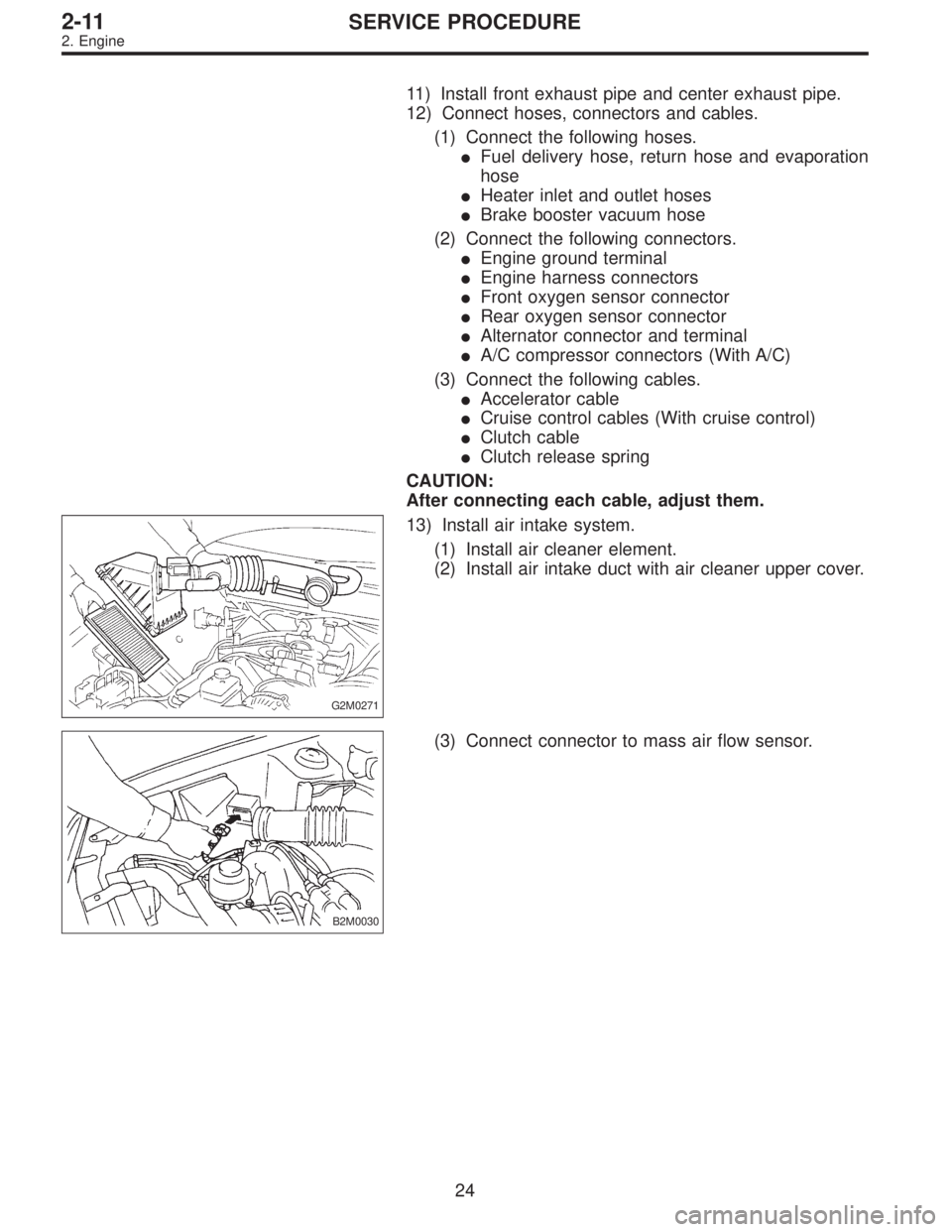
13) Install air intake system.
(1) Install air cleaner element.
(2) Install air intake duct with air cleaner upper cover.
B2M0030
(3) Connect connector to mass air flow sensor.
24
2-11SERVICE PROCEDURE
2. Engine
Page 1655 of 2890
, 100 minutes (AT)
Cold cranking ampere 430 amperes (MT), 490 amperes (AT)
Fuse10 A, 15 A, 20 A
Combination
meterSpeedometer")
1. Body Electrical
A: SPECIFICATIONS
BatteryReserve capacity 82 minutes (MT), 100 minutes (AT)
Cold cranking ampere 430 amperes (MT), 490 amperes (AT)
Fuse10 A, 15 A, 20 A
Combination
meterSpeedometer Electric pulse type
Tachometer Electric impulse type
Water temperature gauge Thermistor cross coil type
Fuel gauge Resistance cross coil type
Charge indicator light 12 V—1.4 W
Brake fluid level warning/parking brake indicator light 12 V—1.4 W
AT oil temperature warning light (AWD only) 12 V—1.4 W
A.B.S. warning light 12 V—1.4 W
CHECK ENGINE warning light
(Malfunction indicator lamp)12 V—1.4 W
Oil pressure warning light 12 V—1.4 W
AIRBAG system warning light 12 V—1.4 W
Low fuel warning light 12 V—3W
FWD indicator light 12 V—1.4 W
TCS warning light 12 V—1.4 W
TCS indicator light 12 V—1.4 W
Turn signal indicator light 12 V—1.4 W (2 pieces)
Seat belt warning light 12 V—1.4 W
Door open warning light 12 V—1.4 W
Headlight beam indicator light 12 V—1.4 W
Meter illumination light12 V—3 W (2 pieces)
12 V—3.4 W (4 pieces)
Headlight 12 V—60/55 W (Halogen)
Front clearance light 12 V—5W
Turn signal lightFront 12 V—21 W
Rear 12 V—21 W
Tail/Stop light 12 V—5/21 W
Back-up light 12 V—21 W
High-mount stop light12 V—18 W (SEDAN), 12 V—13 W
(WAGON)
License plate light 12 V—5W
Room light 12 V—8W
Trunk room light (SEDAN) 12 V—5W
Luggage room light (WAGON) 12 V—5W
Spot light 12 V—8 W (2 pieces)
Glove box light 12 V—3.4 W
Ash tray illumination light 12 V—1.7 W
Selector lever illumination light (AT model) 12 V—1.7 W
2
6-2SPECIFICATIONS
1. Body Electrical
Page 1770 of 2890
 system detects and
indicates a fault in various inputs and outputs of the com-
plex electronic control. CHECK ENGINE malfunction indi-")
1. General
1. GENERAL DESCRIPTION
�The on-board diagnostics (OBD) system detects and
indicates a fault in various inputs and outputs of the com-
plex electronic control. CHECK ENGINE malfunction indi-
cator lamp (MIL) in the combination meter indicates occur-
rence of a fault or trouble.
�Further, against such a failure or sensors as may disable
the drive, the fail-safe function is provided to ensure the
minimal driveability.
�The OBD system incorporated with the vehicles within
this engine family complies with Section 1968.1, California
Code of Regulations (OBD-II regulation). The OBD system
monitors the components and the system malfunction
listed in Engine Section which affects on emissions.
�When the system decides that a malfunction occurs, MIL
illuminates. At the same time of the MIL illumination or
blinking, a diagnostic trouble code (DTC) and a freeze
frame engine conditions are stored into on-board com-
puter.
�The OBD system stores freeze frame engine condition
data (engine load, engine coolant temperature, fuel trim,
engine speed and vehicle speed, etc.) into on-board com-
puter when it detects a malfunction first.
�If the OBD system detects the various malfunctions
including the fault of fuel trim or misfire, the OBD system
first stores freeze frame engine conditions about the fuel
trim or misfire.
�When the malfunction does not occur again for three
consecutive trips, MIL is turned off, but DTC remains at
on-board computer.
�The OBD-II system is capable of communication with a
general scan tool (OBD-II general scan tool) formed by ISO
9141 CARB.
�The OBD-II diagnostics procedure is different from the
usual diagnostics procedure. When troubleshooting OBD-II
vehicles, connect Subaru select monitor or the OBD-II gen-
eral scan tool to the vehicle.
A: ENGINE
1. ENGINE AND EMISSION CONTROL SYSTEM
�The Multipoint Fuel Injection (MFI) system is a system
that supplies the optimum air-fuel mixture to the engine for
all the various operating conditions through the use of the
latest electronic technology.
With this system fuel, which is pressurized at a constant
pressure, is injected into the intake air passage of the cyl-
inder head. The injection quantity of fuel is controlled by an
intermittent injection system where the electro-magnetic
injection valve (fuel injector) opens only for a short period
of time, depending on the quantity of air required for one
cycle of operation. In actual operation, the injection quan-
2
2-7ON-BOARD DIAGNOSTICS II SYSTEM
1. General
Page 1771 of 2890
tity is determined by the duration of an electric pulse
applied to the fuel injector and this permits simple, yet
highly precise metering of the fuel.
�Further, all the operating conditions of the engine are
converted into electric signals, and this results in additional
features of the system, such as large improved
adaptability, easier addition of compensating element, etc.
The MFI system also has the following features:
1) Reduced emission of harmful exhaust gases.
2) Reduced in fuel consumption.
3) Increased engine output.
4) Superior acceleration and deceleration.
5) Superior startability and warm-up performance in cold
weather since compensation is made for coolant and
intake air temperature.
3
2-7ON-BOARD DIAGNOSTICS II SYSTEM
1. General
Page 1773 of 2890

�
2Ignition coil
�
3Ignitor
�
4Crankshaft position sensor
�
5Camshaft position sensor
�
6Throttle position sensor
�
7Fuel injectors
�
8Pressure regulator
�
9Engine coolan")
�1Engine control module (ECM)
�
2Ignition coil
�
3Ignitor
�
4Crankshaft position sensor
�
5Camshaft position sensor
�
6Throttle position sensor
�
7Fuel injectors
�
8Pressure regulator
�
9Engine coolant temperature sensor
�
10Mass air flow sensor
�
11Idle air control solenoid valve
�
12Purge control solenoid valve
�
13Fuel pump
�
14PCV valve
�
15Air cleaner
�
16Canister
�
17Main relay
�
18Fuel pump relay
�
19Fuel filter
�
20Front catalytic converter
�
21Rear catalytic converter
�
22EGR valve (AT vehicles only)
�
23EGR control solenoid valve (AT vehicles only)
�
24Radiator fan�
25Radiator fan relay
�
26Pressure sources switching solenoid valve
�
27Knock sensor
�
28Back-pressure transducer (AT vehicles only)
�
29Front oxygen sensor
�
30Rear oxygen sensor (Except 2200 cc California model)
�
31Pressure sensor
�
32A/C compressor
�
33Inhibitor switch
�
34CHECK ENGINE malfunction indicator lamp (MIL)
�
35Tachometer
�
36A/C relay
�
37A/C control module
�
38Ignition switch
�
39Transmission control module (TCM) (AT vehicles only)
�
40ABS/TCS control module (TCS equipped models)
�
41Vehicle speed sensor
�
42Data link connector (For Subaru select monitor)
�
43Data link connector (For Subaru select monitor and OBD-II
general scan tool)
�
44Two way valve
�
45Rear oxygen sensor (2200 cc California model only)
�
46Filter
5
2-7ON-BOARD DIAGNOSTICS II SYSTEM
1. General
Page 1775 of 2890

�
2Ignition coil
�
3Ignitor
�
4Crankshaft position sensor
�
5Camshaft position sensor
�
6Throttle position sensor
�
7Fuel injectors
�
8Pressure regulator
�
9Engine coolan")
�1Engine control module (ECM)
�
2Ignition coil
�
3Ignitor
�
4Crankshaft position sensor
�
5Camshaft position sensor
�
6Throttle position sensor
�
7Fuel injectors
�
8Pressure regulator
�
9Engine coolant temperature sensor
�
10Mass air flow sensor
�
11Idle air control solenoid valve
�
12Purge control solenoid valve
�
13Fuel pump
�
14PCV valve
�
15Air cleaner
�
16Canister
�
17Main relay
�
18Fuel pump relay
�
19Fuel filter
�
20Front catalytic converter
�
21Rear catalytic converter
�
22EGR valve (AT vehicles only)
�
23EGR control solenoid valve (AT vehicles only)
�
24Radiator fan
�
25Radiator fan relay
�
26Pressure sources switching solenoid valve�
27Front oxygen sensor
�
28Rear oxygen sensor (Except 2200 cc California model)
�
29Pressure sensor
�
30A/C compressor (With A/C models)
�
31Inhibitor switch
�
32CHECK ENGINE malfunction indicator lamp (MIL)
�
33Tachometer
�
34A/C relay (With A/C models)
�
35A/C control module (With A/C models)
�
36Ignition switch
�
37Transmission control module (TCM)
�
38Vehicle speed sensor
�
39Data link connector (For Subaru select monitor)
�
40Data link connector (For Subaru select monitor and OBD-II
general scan tool)
�
41Rear oxygen sensor (2200 cc California model)
�
42Knock sensor
�
43Back-pressure transducer (AT vehicles only)
�
44Filter
�
45Fuel tank pressure sensor
�
46Pressure control solenoid valve
�
47Fuel temperature sensor
�
48Fuel level sensor
�
49Vent control solenoid valve
�
50Air filter
7
2-7ON-BOARD DIAGNOSTICS II SYSTEM
1. General
Page 1777 of 2890

�
2Ignition coil
�
3Ignitor
�
4Crankshaft position sensor
�
5Camshaft position sensor
�
6Throttle position sensor
�
7Fuel injectors
�
8Pressure regulator
�
9Engine coolan")
�1Engine control module (ECM)
�
2Ignition coil
�
3Ignitor
�
4Crankshaft position sensor
�
5Camshaft position sensor
�
6Throttle position sensor
�
7Fuel injectors
�
8Pressure regulator
�
9Engine coolant temperature sensor
�
10Mass air flow sensor
�
11Idle air control solenoid valve
�
12Purge control solenoid valve
�
13Fuel pump
�
14PCV valve
�
15Air cleaner
�
16Canister
�
17Main relay
�
18Fuel pump relay
�
19Fuel filter
�
20Front catalytic converter
�
21Rear catalytic converter
�
22EGR valve�
23EGR control solenoid valve
�
24Radiator fan
�
25Radiator fan relay
�
26Pressure sources switching solenoid valve
�
27Knock sensor
�
28Back-pressure transducer
�
29Front oxygen sensor
�
30Rear oxygen sensor
�
31Pressure sensor
�
32A/C compressor
�
33Inhibitor switch
�
34CHECK ENGINE malfunction indicator lamp (MIL)
�
35Tachometer
�
36A/C relay
�
37A/C control module
�
38Ignition switch
�
39Transmission control module (TCM)
�
40Vehicle speed sensor
�
41Data link connector (Subaru select monitor)
�
42Data link connector (OBD-II general scan tool)
�
43Two way valve
�
44Filter
9
2-7ON-BOARD DIAGNOSTICS II SYSTEM
1. General
Page 1779 of 2890

�
2Ignition coil
�
3Ignitor
�
4Crankshaft position sensor
�
5Camshaft position sensor
�
6Throttle position sensor
�
7Fuel injectors
�
8Pressure regulator
�
9Engine coolan")
�1Engine control module (ECM)
�
2Ignition coil
�
3Ignitor
�
4Crankshaft position sensor
�
5Camshaft position sensor
�
6Throttle position sensor
�
7Fuel injectors
�
8Pressure regulator
�
9Engine coolant temperature sensor
�
10Mass air flow sensor
�
11Idle air control solenoid valve
�
12Purge control solenoid valve
�
13Fuel pump
�
14PCV valve
�
15Air cleaner
�
16Canister
�
17Main relay
�
18Fuel pump relay
�
19Fuel filter
�
20Front catalytic converter
�
21Rear catalytic converter
�
22EGR valve
�
23EGR control solenoid valve�
24Radiator fan
�
25Radiator fan relay
�
26Pressure sources switching solenoid valve
�
27Knock sensor
�
28Back-pressure transducer
�
29Front oxygen sensor
�
30Rear oxygen sensor (Except California model)
�
31Pressure sensor
�
32A/C compressor
�
33Inhibitor switch
�
34CHECK ENGINE malfunction indicator lamp (MIL)
�
35Tachometer
�
36A/C relay
�
37A/C control module
�
38Ignition switch
�
39Transmission control module (TCM)
�
40Vehicle speed sensor 2
�
41Data link connector (For Subaru select monitor)
�
42Data link connector (For Subaru select monitor and OBD-II
general scan tool)
�
43Two way valve
�
44Rear oxygen sensor (California model only)
�
45Filter
11
2-7ON-BOARD DIAGNOSTICS II SYSTEM
1. General