Page 1856 of 2890
8. Diagnostics for Engine Starting
Failure
A: BASIC DIAGNOSTICS CHART
Inspection of starter motor circuit.
Inspection of ECM power supply and ground line.
Inspection of ignition control system.
Inspection of fuel pump circuit.
Inspection of fuel injector circuit.
Inspection of crankshaft position sensor circuit.
Inspection of camshaft position sensor circuit.
Inspection using Subaru select monitor or OBD-II general
scan tool or inspection using“9. General Diagnostics Table
2-7 [T900]”.
�
�
�
�
�
�
�
88
2-7ON-BOARD DIAGNOSTICS II SYSTEM
8. Diagnostics for Engine Starting Failure
Page 1868 of 2890
 Remove plug cord cap from each spark plug.
2) Install new spark plug on plug cord cap.
CAUTION:
Do not remove spark plug from engine.
3) Cont")
OBD0727A
B2M0644A
8D1
CHECK IGNITION SYSTEM FOR SPARKS.
1) Remove plug cord cap from each spark plug.
2) Install new spark plug on plug cord cap.
CAUTION:
Do not remove spark plug from engine.
3) Contact spark plug’s thread portion on engine.
4) While opening throttle valve fully, crank engine to check
that spark occurs at each cylinder.
: Does spark occur at each cylinder?
: Check fuel pump system.
: Go to step8D2.
OBD0123A
8D2CHECK POWER SUPPLY CIRCUIT FOR
IGNITION COIL.
1) Turn ignition switch to OFF.
2) Disconnect connector from ignition coil.
3) Turn ignition switch to ON.
4) Measure power supply voltage between ignition coil
connector and engine ground.
: Connector & terminal
(E12) No. 2 (+)—Engine ground (�):
Is the voltage more than 10 V?
: Go to step8D3.
: Repair harness between ignition coil and ignition
switch connector.
OBD0124
8D3
CHECK IGNITION COIL.
1) Measure resistance between ignition coil terminals to
check primary coil.
: Terminals
No. 2—No. 1:
Is the resistance between 0.4 and 1.0Ω?
: Go to next.
: Replace ignition coil.
100
2-7ON-BOARD DIAGNOSTICS II SYSTEM
8. Diagnostics for Engine Starting Failure
Page 1871 of 2890
 Disconnect connector from ECM.
2) Measure resistance of harness connector between
ECM and ignitor.
: Connector & terminal
(B84) No. 41�")
B2M0523A
8D7CHECK HARNESS BETWEEN ECM AND
IGNITOR CONNECTOR.
1) Disconnect connector from ECM.
2) Measure resistance of harness connector between
ECM and ignitor.
: Connector & terminal
(B84) No. 41—(B13) No. 1:
Is the resistance less than 1Ω?
: Go to next.
: Repair open circuit in harness between ECM and
ignitor connector.
: Connector & terminal
(B84) No. 40—(B13) No. 2:
Is the resistance less than 1Ω?
: Go to next.
: : Repair open circuit in harness between ECM
and ignitor connector.
: Connector & terminal
(B84) No. 94—(B13) No. 3:
Is the resistance less than 1Ω?
: Repair open circuit in harness between ECM and
ignitor connector.
: Go to next step 3).
B2M0524A
3) Measure resistance of harness connector between
ECM and chassis ground.
: Connector & terminal
(B84) No. 41—Chassis ground:
Is the resistance more than 1 MΩ?
: Go to next.
: Repair short circuit in harness between ECM and
ignitor connector.
: Connector & terminal
(B84) No. 40—Chassis ground:
Is the resistance more than 1 MΩ?
: Go to next.
: Repair short circuit in harness between ECM and
ignitor connector.
: Is there poor contact in ECM connector?
: Repair poor contact in ECM connector.
: Check fuel pump circuit.
103
2-7ON-BOARD DIAGNOSTICS II SYSTEM
8. Diagnostics for Engine Starting Failure
Page 1872 of 2890
E: FUEL PUMP CIRCUIT (2200CC FWD,
2500CC AWD TAIWAN MODEL)
8E1Check operating sound of fuel pump.
8E2Check ground circuit of fuel pump.
8E3Check power supply to fuel pump.
8E4Check harness between fuel pump and fuel
pump relay connector.
8E5Check fuel pump relay.
8E6Check harness between ECM and fuel pump
relay connector.
CAUTION:
After repair or replacement of faulty parts, conduct
CLEAR MEMORY and INSPECTION MODES.
�
�
�
�
�
104
2-7ON-BOARD DIAGNOSTICS II SYSTEM
8. Diagnostics for Engine Starting Failure
Page 1874 of 2890
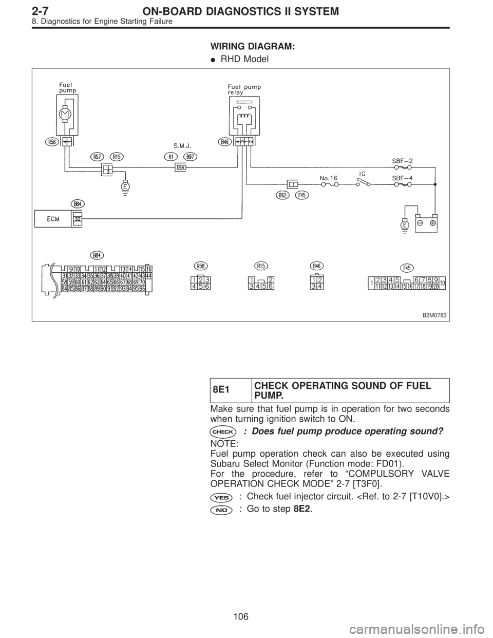
WIRING DIAGRAM:
�RHD Model
B2M0783
8E1CHECK OPERATING SOUND OF FUEL
PUMP.
Make sure that fuel pump is in operation for two seconds
when turning ignition switch to ON.
: Does fuel pump produce operating sound?
NOTE:
Fuel pump operation check can also be executed using
Subaru Select Monitor (Function mode: FD01).
For the procedure, refer to“COMPULSORY VALVE
OPERATION CHECK MODE”2-7 [T3F0].
: Check fuel injector circuit.
: Go to step8E2.
106
2-7ON-BOARD DIAGNOSTICS II SYSTEM
8. Diagnostics for Engine Starting Failure
Page 1875 of 2890
 Turn ignition switch to OFF.
2) Disconnect connector from fuel pump.
3) Measure resistance of harness connector between fuel
pump and chassis ground.")
OBD0132A
8E2CHECK GROUND CIRCUIT OF FUEL
PUMP.
1) Turn ignition switch to OFF.
2) Disconnect connector from fuel pump.
3) Measure resistance of harness connector between fuel
pump and chassis ground.
: Connector & terminal
(R58) No. 4—Chassis ground:
Is the resistance less than 5Ω?
: Go to step8E3.
: Repair open circuit in fuel pump ground circuit.
OBD0133A
8E3
CHECK POWER SUPPLY TO FUEL PUMP.
1) Turn ignition switch to ON.
2) Measure voltage of power supply circuit between fuel
pump connector and chassis ground.
: Connector & terminal
(R58) No. 1 (+)—Chassis ground (�):
Is the voltage more than 10 V?
: Replace fuel pump.
: Go to step8E4.
B2M0526A
8E4CHECK HARNESS BETWEEN FUEL
PUMP AND FUEL PUMP RELAY CON-
NECTOR.
1) Turn ignition switch to OFF.
2) Measure resistance of harness connector between fuel
pump and fuel pump relay.
: Connector & terminal
(R58) No. 1—(B46) No. 4:
Is the resistance less than 1Ω?
: Go to next.
: Repair open circuit in harness between fuel pump
and fuel pump relay connector.
: Connector & terminal
(R58) No. 1—Chassis ground:
Is the resistance more than 1 MΩ?
: Go to step8E5.
: Repair short circuit in harness between fuel pump
and fuel pump relay connector.
107
2-7ON-BOARD DIAGNOSTICS II SYSTEM
8. Diagnostics for Engine Starting Failure
Page 1876 of 2890
G2M0461
8E5
CHECK FUEL PUMP RELAY.
1) Disconnect connectors from fuel pump relay and main
relay.
2) Remove fuel pump relay and main relay with bracket.
3) Connect battery to fuel pump relay connector terminals
No. 1 and No. 3.
4) Measure resistance between connector terminals of
fuel pump relay.
: Terminals
No. 2—No. 4:
Is the resistance less than 10Ω?
: Go to step8E6.
: Replace fuel pump relay.
B2M0527A
8E6CHECK HARNESS BETWEEN ECM AND
FUEL PUMP RELAY CONNECTOR.
1) Disconnect connectors from ECM.
2) Measure resistance of harness between ECM and fuel
pump relay connector.
: Connector & terminal
(B84) No. 32—(B46) No. 3:
Is the resistance less than 1Ω?
: Go to next.
: Repair harness between ECM and fuel pump
relay connector.
: Is there poor contact in ECM connector?
: Repair poor contact in ECM connector.
: Check fuel injector circuit.
108
2-7ON-BOARD DIAGNOSTICS II SYSTEM
8. Diagnostics for Engine Starting Failure
Page 1877 of 2890
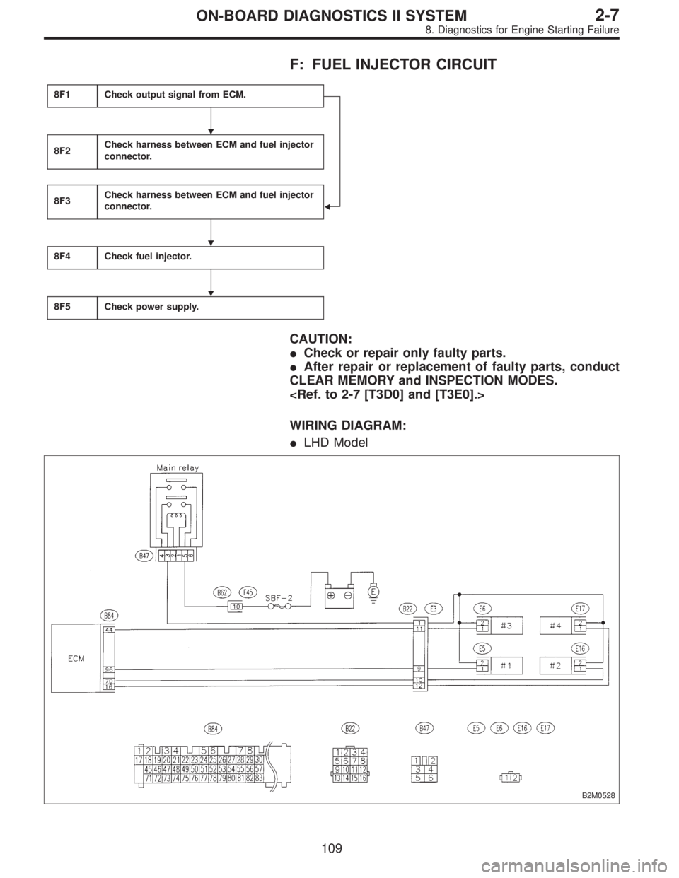
F: FUEL INJECTOR CIRCUIT
8F1Check output signal from ECM.
�
8F2Check harness between ECM and fuel injector
connector.
8F3Check harness between ECM and fuel injector
connector.
8F4Check fuel injector.
8F5Check power supply.
CAUTION:
�Check or repair only faulty parts.
�After repair or replacement of faulty parts, conduct
CLEAR MEMORY and INSPECTION MODES.
WIRING DIAGRAM:
�LHD Model
B2M0528
�
�
�
109
2-7ON-BOARD DIAGNOSTICS II SYSTEM
8. Diagnostics for Engine Starting Failure


8E1Check operating sound of fuel pump.
8E2Check ground circuit of fuel pump.
8E3Check power supply to fuel pump.
8E4Check harness between fue")
 Disconnect connectors from fuel pump relay and main
relay.
2) Remove fuel pump relay and main relay with bracket.
3) Connect battery to fuel pump relay connector")