Page 1878 of 2890
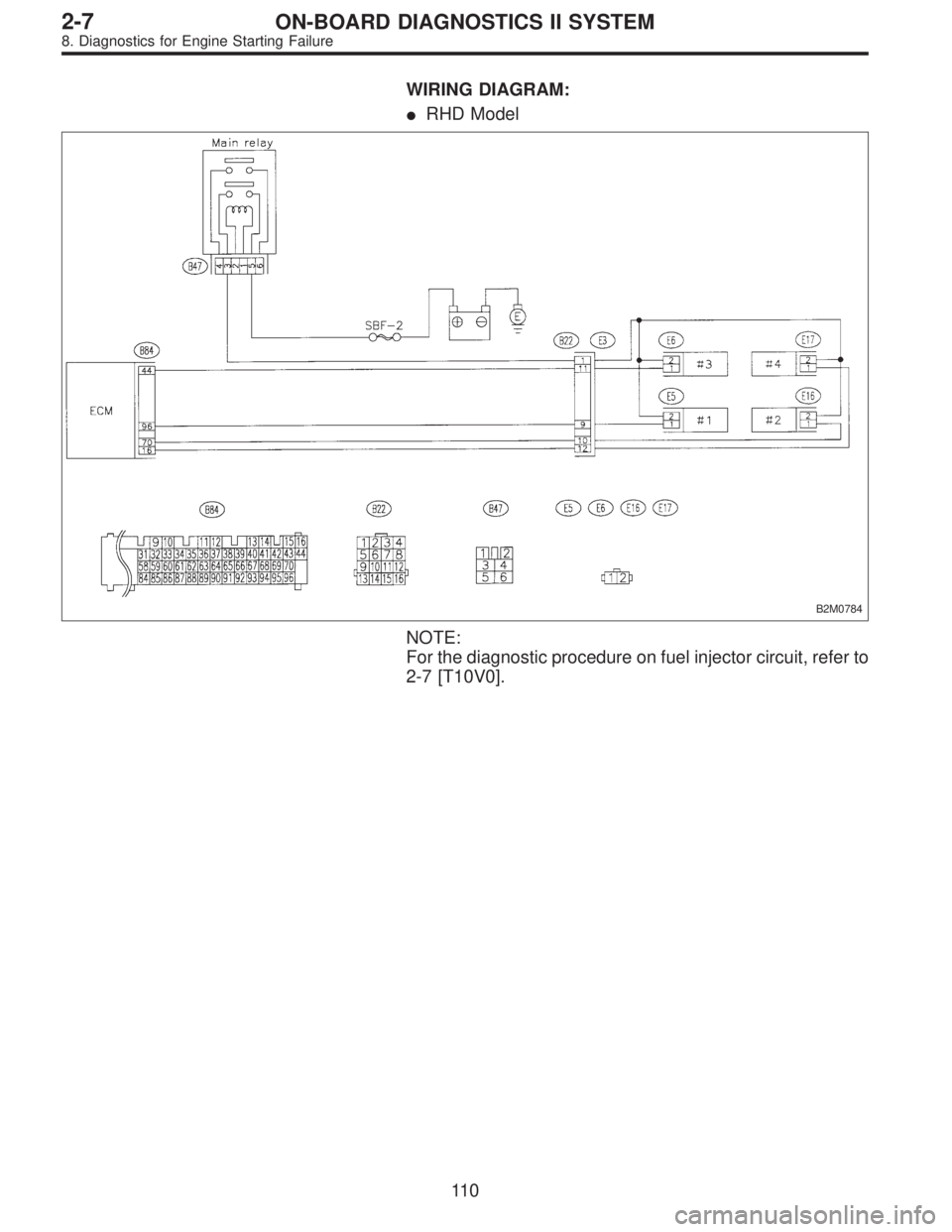
WIRING DIAGRAM:
�RHD Model
B2M0784
NOTE:
For the diagnostic procedure on fuel injector circuit, refer to
2-7 [T10V0].
11 0
2-7ON-BOARD DIAGNOSTICS II SYSTEM
8. Diagnostics for Engine Starting Failure
Page 1881 of 2890
I: FUEL PUMP CIRCUIT (2200 cc AWD
EXCEPT TAIWAN MODEL)
8I1Check operating sound of fuel pump.
8I2Check ground circuit of fuel pump.
8I3Check power supply to fuel pump.
8I4Check harness between fuel pump and fuel
pump relay connector.
8I5Check fuel pump relay.
8I6Check harness between ECM and fuel pump
relay connector.
CAUTION:
After repair or replacement of faulty parts, conduct
CLEAR MEMORY and INSPECTION MODES.
�
�
�
�
�
11 3
2-7ON-BOARD DIAGNOSTICS II SYSTEM
8. Diagnostics for Engine Starting Failure
Page 1883 of 2890
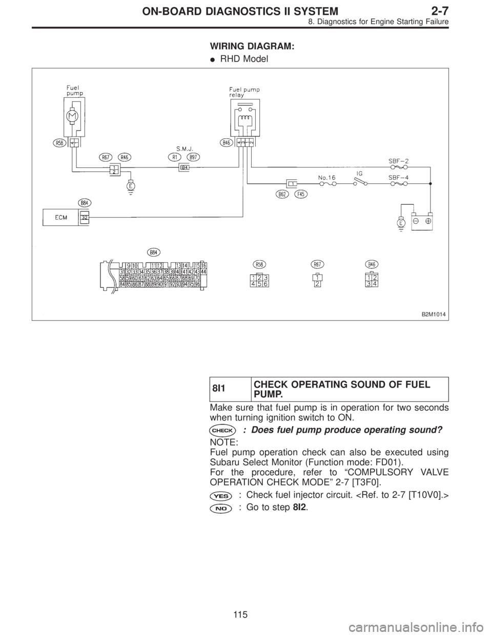
WIRING DIAGRAM:
�RHD Model
B2M1014
8I1CHECK OPERATING SOUND OF FUEL
PUMP.
Make sure that fuel pump is in operation for two seconds
when turning ignition switch to ON.
: Does fuel pump produce operating sound?
NOTE:
Fuel pump operation check can also be executed using
Subaru Select Monitor (Function mode: FD01).
For the procedure, refer to“COMPULSORY VALVE
OPERATION CHECK MODE”2-7 [T3F0].
: Check fuel injector circuit.
: Go to step8I2.
11 5
2-7ON-BOARD DIAGNOSTICS II SYSTEM
8. Diagnostics for Engine Starting Failure
Page 1884 of 2890
 Turn ignition switch to OFF.
2) Disconnect connector from fuel pump.
3) Measure resistance of harness connector between fuel
pump and chassis ground.")
OBD0132A
8I2CHECK GROUND CIRCUIT OF FUEL
PUMP.
1) Turn ignition switch to OFF.
2) Disconnect connector from fuel pump.
3) Measure resistance of harness connector between fuel
pump and chassis ground.
: Connector & terminal
(R58) No. 4—Chassis ground:
Is the resistance less than 5Ω?
: Go to step8I3.
: Repair open circuit in fuel pump ground circuit.
OBD0133A
8I3
CHECK POWER SUPPLY TO FUEL PUMP.
1) Turn ignition switch to ON.
2) Measure voltage of power supply circuit between fuel
pump connector and chassis ground.
: Connector & terminal
(R58) No. 1 (+)—Chassis ground (�):
Is the voltage more than 10 V?
: Replace fuel pump.
: Go to step8I4.
B2M0526A
8I4CHECK HARNESS BETWEEN FUEL
PUMP AND FUEL PUMP RELAY CON-
NECTOR.
1) Turn ignition switch to OFF.
2) Measure resistance of harness connector between fuel
pump and fuel pump relay.
: Connector & terminal
(R58) No. 1—(B46) No. 4:
Is the resistance less than 1Ω?
: Go to next.
: Repair open circuit in harness between fuel pump
and fuel pump relay connector.
: Connector & terminal
(R58) No. 1—Chassis ground:
Is the resistance more than 1 MΩ?
: Go to step8I5.
: Repair short circuit in harness between fuel pump
and fuel pump relay connector.
11 6
2-7ON-BOARD DIAGNOSTICS II SYSTEM
8. Diagnostics for Engine Starting Failure
Page 1885 of 2890
G2M0461
8I5
CHECK FUEL PUMP RELAY.
1) Disconnect connectors from fuel pump relay and main
relay.
2) Remove fuel pump relay and main relay with bracket.
3) Connect battery to fuel pump relay connector terminals
No. 1 and No. 3.
4) Measure resistance between connector terminals of
fuel pump relay.
: Terminals
No. 2—No. 4:
Is the resistance less than 10Ω?
: Go to step8I6.
: Replace fuel pump relay.
B2M0527A
8I6CHECK HARNESS BETWEEN ECM AND
FUEL PUMP RELAY CONNECTOR.
1) Disconnect connectors from ECM.
2) Measure resistance of harness between ECM and fuel
pump relay connector.
: Connector & terminal
(B84) No. 32—(B46) No. 3:
Is the resistance less than 1Ω?
: Go to next.
: Repair harness between ECM and fuel pump
relay connector.
: Is there poor contact in ECM connector?
: Repair poor contact in ECM connector.
: Check fuel injector circuit.
11 7
2-7ON-BOARD DIAGNOSTICS II SYSTEM
8. Diagnostics for Engine Starting Failure
Page 1886 of 2890

Throttle position sensor
Crankshaft position sensor & Camshaft po")
9. General Diagnostics Table
1. FOR ENGINE
12345678910111213
Problem parts
Mass air flow sensor
Engine coolant temperature sensor (*1)
Throttle position sensor
Crankshaft position sensor & Camshaft position sensor (*2)
Idle air control solenoid valve
Knock sensor
Purge control solenoid valve
EGR valve
Fuel injection parts (*3)
Ignition parts (*4)
Fuel pump and relay
A/C switch and A/C cut relay
Engine torque control signal circuitSymptom
1 Engine stalls during idling.�� � � ���
2 Rough idling�� � � � �
3 Engine does not return to idle.���
4 Poor acceleration�� � � ���
5Engine stalls or engine sags or hesi-
tates at acceleration.�� � � ��� �
6 Surge�� � �� �
7 Spark knock����
8 After burning in exhaust system�� � �
*1: The mark,�, indicates the symptom occurring only in cold temperatures.
*2: For items with the mark,�, ensure the secure installation of crankshaft position sensor and camshaft position sensor. Replacement is
not necessary.
*3: Check fuel injector, fuel pressure regulator and fuel filter.
*4: Check ignitor, ignition coil and spark plug.
NOTE:
Malfunction of parts other than the above is also possible. Refer to 1. Engine Trouble in General [K100] in Repair Section 2-3 or 2-3b of
the Service Manual.
11 8
2-7ON-BOARD DIAGNOSTICS II SYSTEM
9. General Diagnostics Table
Page 1891 of 2890
 LIST
DTC
No.Abbreviation
(Subaru select monitor)Item Page
P0100 QA Mass air flow sensor circuit malfunction 125
P0101 QA
—R M")
10. Diagnostics Chart with Trouble
Code
A: DIAGNOSTIC TROUBLE CODE (DTC) LIST
DTC
No.Abbreviation
(Subaru select monitor)Item Page
P0100 QA Mass air flow sensor circuit malfunction 125
P0101 QA
—R Mass air flow sensor circuit range/performance problem 132
P0105 P
—S Pressure sensor circuit malfunction 134
P0106 PS
—R Pressure sensor circuit range/performance problem 142
P0115 TW Engine coolant temperature sensor circuit malfunction 147
P0120 THV Throttle position sensor circuit malfunction 151
P0121 TH
—R Throttle position sensor circuit range/performance problem 157
P0125 TW
—CL Insufficient coolant temperature for closed loop fuel control 159
P0130 FO2
—V Front oxygen sensor circuit malfunction 161
P0133 FO2
—R Front oxygen sensor circuit slow response 164
P0135 FO2H Front oxygen sensor heater circuit malfunction 166
P0136 RO2
—V Rear oxygen sensor circuit malfunction 172
P0139 RO2
—R Rear oxygen sensor circuit slow response 177
P0141 RO2H Rear oxygen sensor heater circuit malfunction 179
P0170 FUEL Fuel trim malfunction 185
P0180 TNKT Fuel temperature sensor A circuit malfunction 190
P0181 TNKT
—F Fuel temperature sensor A circuit range/performance problem 195
P0201 INJ1 Fuel injector circuit malfunction - #1
197 P0202 INJ2 Fuel injector circuit malfunction - #2
P0203 INJ3 Fuel injector circuit malfunction - #3
P0204 INJ4 Fuel injector circuit malfunction - #4
P0301 MIS
—1 Cylinder 1 misfire detected
203 P0302 MIS
—2 Cylinder 2 misfire detected
P0303 MIS
—3 Cylinder 3 misfire detected
P0304 MIS
—4 Cylinder 4 misfire detected
P0325 KNOCK Knock sensor circuit malfunction 211
P0335 CRANK Crankshaft position sensor circuit malfunction 215
P0340 CAM Camshaft position sensor circuit malfunction 218
P0400 EGR Exhaust gas recirculation flow malfunction 221
P0403 EGRSOL Exhaust gas recirculation circuit malfunction 227
P0420 CAT Catalyst system efficiency below threshold 233
P0440 EVAP Evaporative emission control system malfunction 236
P0441 CPC
—F Evaporative emission control system incorrect purge flow 241
P0443 CPC Evaporative emission control system purge control valve circuit malfunction 244
P0446 VCMSOL Evaporative emission control system vent control malfunction 249
P0450 TNKP Evaporative emission control system pressure sensor malfunction 255
P0451 TNKP
—F Evaporative emission control system pressure sensor range/performance problem 264
123
2-7ON-BOARD DIAGNOSTICS II SYSTEM
10. Diagnostics Chart with Trouble Code
Page 1892 of 2890
Item Page
P0500 VSP Vehicle speed sensor malfunction 266
P0505 ISC Idle control system malfunction 269
P0506 ISC
—L Idle control system RPM lower than expe")
DTC
No.Abbreviation
(Subaru select monitor)Item Page
P0500 VSP Vehicle speed sensor malfunction 266
P0505 ISC Idle control system malfunction 269
P0506 ISC
—L Idle control system RPM lower than expected 276
P0507 ISC
—H Idle control system RPM higher than expected 277
P0600—Serial communication link malfunction 278
P0601 RAM Internal control module memory check sum error 281
P0703 ATBRK Brake switch input malfunction 283
P0705 ATRNG Transmission range sensor circuit malfunction 286
P0710 ATF Transmission fluid temperature sensor circuit malfunction 293
P0720 ATVSP Output speed sensor (vehicle speed sensor 1) circuit malfunction 294
P0725 ATNE Engine speed input circuit malfunction 295
P0731 ATGR1 Gear 1 incorrect ratio
296 P0732 ATGR2 Gear 2 incorrect ratio
P0733 ATGR3 Gear 3 incorrect ratio
P0734 ATGR4 Gear 4 incorrect ratio
P0740 ATLU
—F Torque converter clutch system malfunction 300
P0743 ATLU Torque converter clutch system electrical 304
P0748 ATPL Pressure control solenoid electrical 305
P0753 ATSFT1 Shift solenoid A electrical 306
P0758 ATSFT2 Shift solenoid B electrical 307
P0760 ATOVR
—F Shift solenoid C malfunction 308
P0763 ATOVR Shift solenoid C electrical 312
P1100 ST
—SW Starter switch circuit malfunction 313
P1101 N/P
—SW Neutral position switch circuit malfunction [MT vehicles] 315
P1101 N/P
—SW Neutral position switch circuit malfunction [AT vehicles] 318
P1102 BR Pressure sources switching solenoid valve circuit malfunction 322
P1103 TRQ Engine torque control signal circuit malfunction 328
P1400 PCVSOL Fuel tank pressure control solenoid valve circuit malfunction 331
P1401 PCV
—F Fuel tank pressure control system function problem 337
P1402 FLVL Fuel level sensor circuit malfunction 339
P1500 FAN
—1 Radiator fan relay 1 circuit malfunction 351
P1502 FAN
—F Radiator fan function problem 358
P1700 ATTH Throttle position sensor circuit malfunction for automatic transmission 361
P1701 ATCRS Cruise control set signal circuit malfunction for automatic transmission 362
P1702 ATDIAG Automatic transmission diagnosis input signal circuit malfunction 365
P0461*1 EXERR22 Fuel level sensor circuit range/performance problem 368
*1: Only OBD-II general scan tool displays DTC.
124
2-7ON-BOARD DIAGNOSTICS II SYSTEM
10. Diagnostics Chart with Trouble Code

8I1Check operating sound of fuel pump.
8I2Check ground circuit of fuel pump.
8I3Check power supply to fuel pump.
8I4Check harness between fuel pu")
 Disconnect connectors from fuel pump relay and main
relay.
2) Remove fuel pump relay and main relay with bracket.
3) Connect battery to fuel pump relay connector")