Page 478 of 2890
G2M0376
2) Install oil strainer onto baffle plate.
CAUTION:
Replace O-ring with a new one.
Tightening torque:
9.8 N⋅m (1.0 kg-m, 7 ft-lb)
G2M0082
3) Hold oil strainer to oil strainer stay.
Tightening torque:
9.8 N⋅m (1.0 kg-m, 7 ft-lb)
G2M0084
4) Apply fluid packing to mating surfaces and install oil
pan.
Fluid packing:
THREE BOND 1207C or equivalent
G2M0081
5) Tighten bolts which install oil pan onto engine block.
Tightening torque:
9.8 N⋅m (1.0 kg-m, 7 ft-lb)
6) Tighten drain plug.
Tightening torque:
44
+4.8
0N⋅m (4.5+0.5
0kg-m, 33+3.6
0ft-lb)
CAUTION:
Replace drain plug gasket with new one.
B2M0743A
7) Lower engine onto front crossmember.
8) Tighten nuts which install front cushion rubber onto front
crossmember.
Tightening torque:
69±15 N⋅m (7.0±1.5 kg-m, 51±11 ft-lb)
12
2-4SERVICE PROCEDURE
2. Oil Pan and Oil Strainer
Page 479 of 2890
B2M0054
9) Install front exhaust pipe.
CAUTION:
Always use the new gaskets.
(1) Place front exhaust pipe on bracket.
(2) Tighten nuts which install front exhaust pipe on
engine.
Tightening torque:
30±5 N⋅m (3.1±0.5 kg-m, 22.4±3.6 ft-lb)
B2M0055
(3) Tighten nuts which install front catalytic converter to
center exhaust pipe.
Tightening torque:
35±5 N⋅m (3.6±0.5 kg-m, 26.0±3.6 ft-lb)
B2M0056
(4) Tighten bolt which installs front exhaust pipe on
bracket.
Tightening torque:
24±3 N⋅m (2.4±0.3 kg-m, 17.4±2.2 ft-lb)
B2M0312
10) Connect connector to rear oxygen sensor. (Except
California 2200 cc model)
B2M0053
11) Lower the vehicle.
CAUTION:
At this time, lower lifting device and release steel
cables.
12) Remove lifting device and steel cables.
13
2-4SERVICE PROCEDURE
2. Oil Pan and Oil Strainer
Page 480 of 2890
B2M0724
13) Connect connector to front oxygen sensor.
B2M0725
14) Connect connector to rear oxygen sensor. (California
2200 cc model only)
G2M0302
15) Install pitching stopper.
Tightening torque:
T1: 49±5 N⋅m (5.0±0.5 kg-m, 36.2±3.6 ft-lb)
T2: 57±10 N⋅m (5.8±1.0 kg-m, 42±7 ft-lb)
B2M0320
16) Install radiator upper brackets.
Tightening torque:
12±3 N⋅m (1.2±0.3 kg-m, 8.7±2.2 ft-lb)
B2M0321
17) Install air intake duct.
18) Fill engine oil through filler pipe up to upper point of
level gauge.
Engine oil capacity:
2200 cc ; Upper level
4.0�(4.2 US qt, 3.5 Imp qt)
Lower level
3.0�(3.2 US qt, 2.6 Imp qt)
2500 cc ; Upper level
4.5�(4.8 US qt, 4.0 Imp qt)
14
2-4SERVICE PROCEDURE
2. Oil Pan and Oil Strainer
Page 483 of 2890
G2M0091
B: INSTALLATION
1) Install oil pressure switch onto engine block.
Tightening torque:
25±3 N⋅m (2.5±0.3 kg-m, 18.1±2.2 ft-lb)
2) Connect terminal of oil pressure switch.
G2M0090
3) Install generator on bracket and temporary tighten
installing bolts.
B2M0017
4) Install front side V-belt and adjust it.
5) Install V-belt cover.
G2M0088
6) Connect connector and terminal to generator.
16
2-4SERVICE PROCEDURE
3. Oil Pressure Switch
Page 484 of 2890

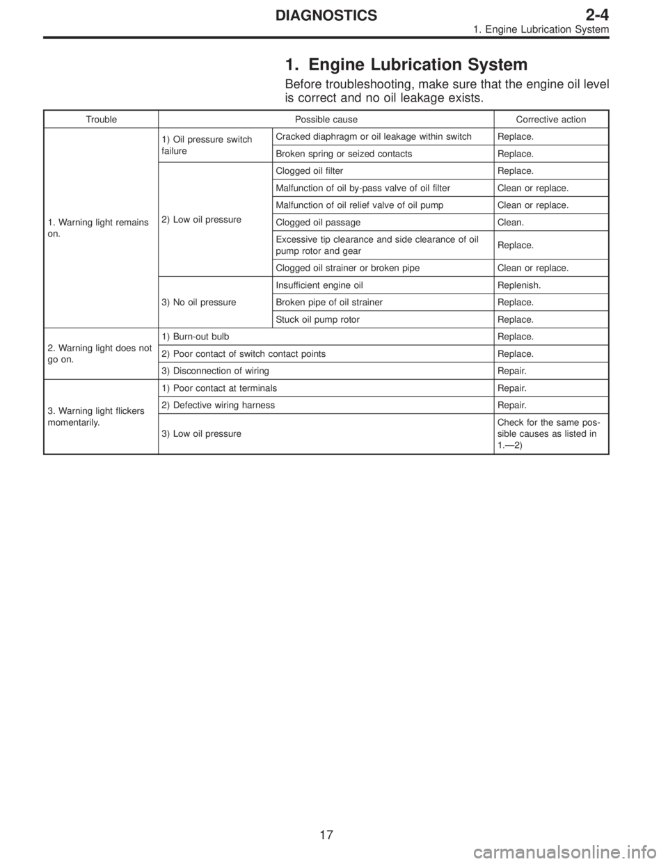
1. Engine Lubrication System
Before troubleshooting, make sure that the engine oil level
is correct and no oil leakage exists.
Trouble Possible cause Corrective action
1. Warning light remains
on.1) Oil pressure switch
failureCracked diaphragm or oil leakage within switch Replace.
Broken spring or seized contacts Replace.
2) Low oil pressureClogged oil filter Replace.
Malfunction of oil by-pass valve of oil filter Clean or replace.
Malfunction of oil relief valve of oil pump Clean or replace.
Clogged oil passage Clean.
Excessive tip clearance and side clearance of oil
pump rotor and gearReplace.
Clogged oil strainer or broken pipe Clean or replace.
3) No oil pressureInsufficient engine oil Replenish.
Broken pipe of oil strainer Replace.
Stuck oil pump rotor Replace.
2. Warning light does not
go on.1) Burn-out bulb Replace.
2) Poor contact of switch contact points Replace.
3) Disconnection of wiring Repair.
3. Warning light flickers
momentarily.1) Poor contact at terminals Repair.
2) Defective wiring harness Repair.
3) Low oil pressureCheck for the same pos-
sible causes as listed in
1.—2)
17
2-4DIAGNOSTICS
1. Engine Lubrication System
Page 503 of 2890

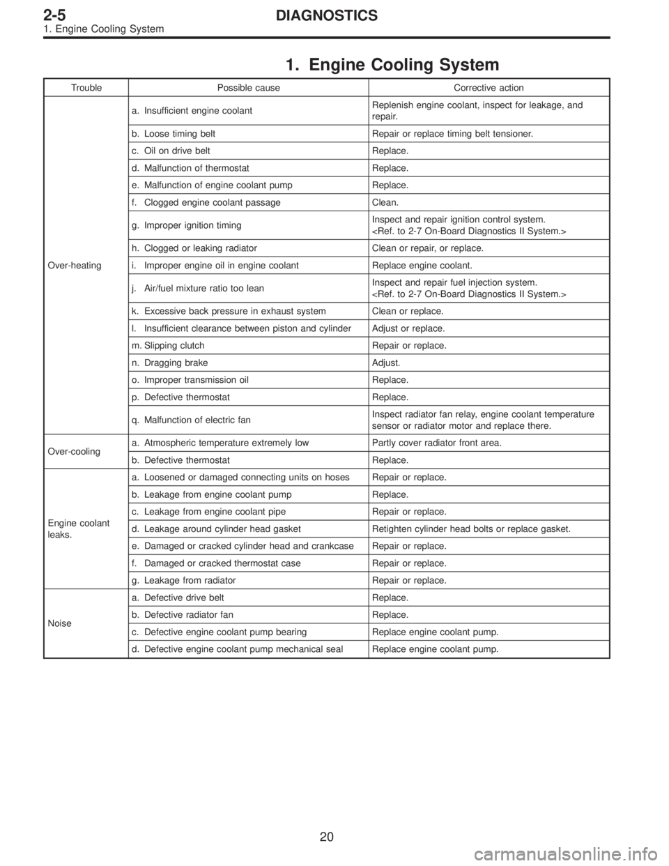
1. Engine Cooling System
Trouble Possible cause Corrective action
Over-heatinga. Insufficient engine coolantReplenish engine coolant, inspect for leakage, and
repair.
b. Loose timing belt Repair or replace timing belt tensioner.
c. Oil on drive belt Replace.
d. Malfunction of thermostat Replace.
e. Malfunction of engine coolant pump Replace.
f. Clogged engine coolant passage Clean.
g. Improper ignition timingInspect and repair ignition control system.
h. Clogged or leaking radiator Clean or repair, or replace.
i. Improper engine oil in engine coolant Replace engine coolant.
j. Air/fuel mixture ratio too leanInspect and repair fuel injection system.
k. Excessive back pressure in exhaust system Clean or replace.
l. Insufficient clearance between piston and cylinder Adjust or replace.
m. Slipping clutch Repair or replace.
n. Dragging brake Adjust.
o. Improper transmission oil Replace.
p. Defective thermostat Replace.
q. Malfunction of electric fanInspect radiator fan relay, engine coolant temperature
sensor or radiator motor and replace there.
Over-coolinga. Atmospheric temperature extremely low Partly cover radiator front area.
b. Defective thermostat Replace.
Engine coolant
leaks.a. Loosened or damaged connecting units on hoses Repair or replace.
b. Leakage from engine coolant pump Replace.
c. Leakage from engine coolant pipe Repair or replace.
d. Leakage around cylinder head gasket Retighten cylinder head bolts or replace gasket.
e. Damaged or cracked cylinder head and crankcase Repair or replace.
f. Damaged or cracked thermostat case Repair or replace.
g. Leakage from radiator Repair or replace.
Noisea. Defective drive belt Replace.
b. Defective radiator fan Replace.
c. Defective engine coolant pump bearing Replace engine coolant pump.
d. Defective engine coolant pump mechanical seal Replace engine coolant pump.
20
2-5DIAGNOSTICS
1. Engine Cooling System
Page 527 of 2890
B2M0334
(3) Remove bolts which install power steering pump
from bracket.
B2M0029
(4) Place power steering pump on the right side wheel
apron.
B6M0160
8) Disconnect spark plug cords from ignition coil.
H2M1246
9) Disconnect engine coolant hoses from throttle body.
H2M1259A
10) Disconnect engine coolant hose�1from idle air con-
trol solenoid valve.
11) Disconnect air by-pass hose�
2from idle air control
solenoid valve.
9
2-7SERVICE PROCEDURE
4. Intake Manifold
Page 530 of 2890
B2M0159
22) Remove bolts which hold intake manifold onto cylinder
heads.
B2M0160
23) Remove intake manifold.
B2M0757A
B: DISASSEMBLY
1) Disconnect engine ground terminal from intake mani-
fold.
B2M0347A
2) Disconnect connectors from throttle position sensor,
ignition coil, fuel injectors, idle air control solenoid valve,
purge control solenoid valve and EGR solenoid valve.
3) Remove engine harness from intake manifold.
�
1EGR solenoid valve
�
2Throttle position sensor
�
3Idle air control solenoid valve
�
4Purge control solenoid valve
�
5Harness band
H2M1247
4) Remove idle air control solenoid valve from intake
manifold.
12
2-7SERVICE PROCEDURE
4. Intake Manifold