Page 636 of 2890
G2M0370
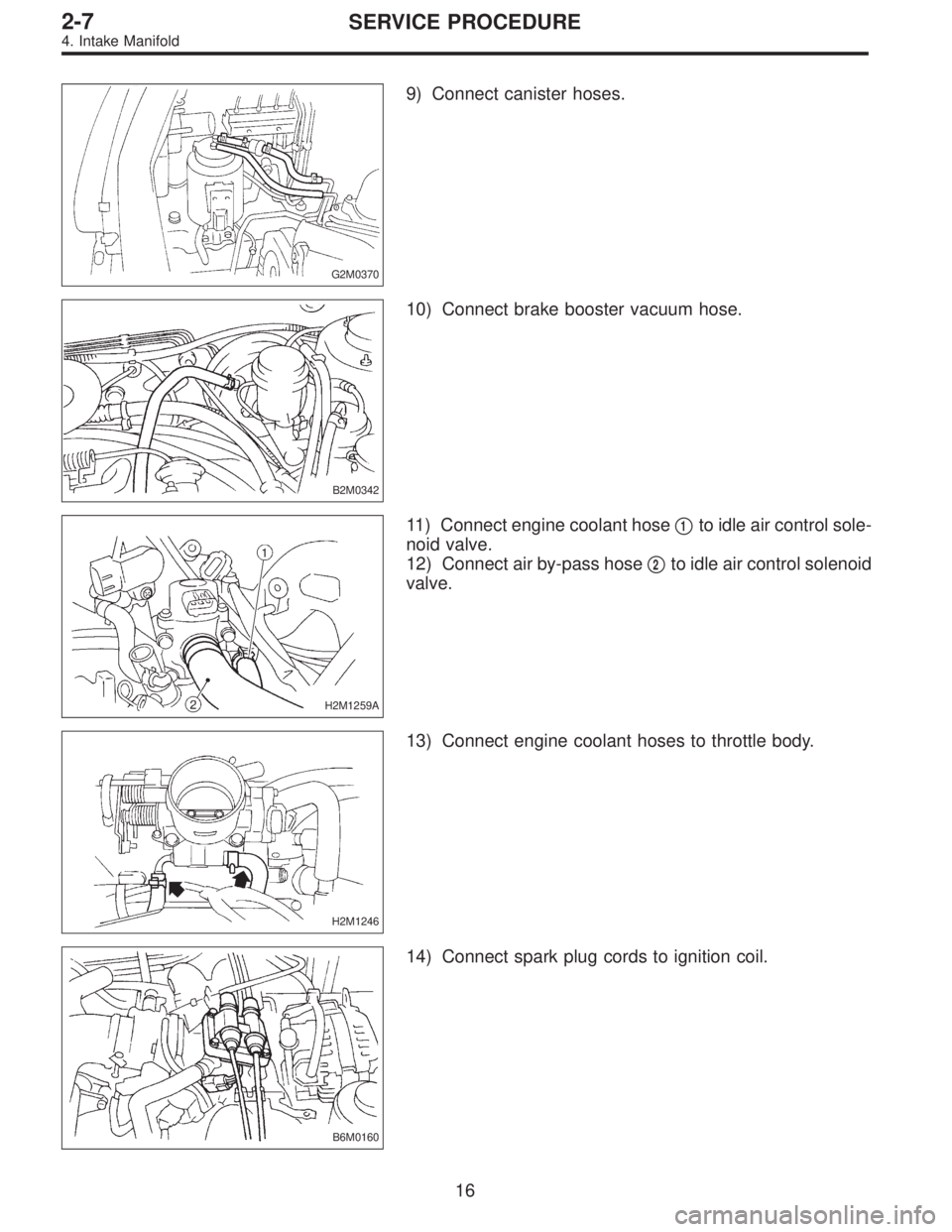
9) Connect canister hoses.
B2M0342
10) Connect brake booster vacuum hose.
H2M1259A
11) Connect engine coolant hose�1to idle air control sole-
noid valve.
12) Connect air by-pass hose�
2to idle air control solenoid
valve.
H2M1246
13) Connect engine coolant hoses to throttle body.
B6M0160
14) Connect spark plug cords to ignition coil.
16
2-7SERVICE PROCEDURE
4. Intake Manifold
Page 707 of 2890
 While pushing release lever�
3to pivot and twisting it to
both sides, fit retainer spring�
5onto the constricted portion
of pivot.
NOTE:
Confirm that retaine")
B2M0633A
1. MECHANICAL APPLICATION TYPE
1) While pushing release lever�
3to pivot and twisting it to
both sides, fit retainer spring�
5onto the constricted portion
of pivot.
NOTE:
Confirm that retainer spring is securely fitted by observing
it through the main case hole.
2) Install release bearing�
6and fasten it with two clips�2.
3) Install release lever seal�
4.
G2M0235
4) After remounting engine and transmission on body,
make adjustment of the clutch release lever end play.
CAUTION:
Take care not to twist the cable during adjustment.
5) Install release lever return spring (Models without hill
holder only).
NOTE:
Hook up the return spring to right side hole of the release
lever.
G2M0242
4. Clutch Disc and Cover
A: REMOVAL
1) Install ST on flywheel.
ST 498497100 CRANKSHAFT STOPPER
2) Remove clutch cover and clutch disc.
CAUTION:
�Take care not to allow oil on the clutch disc facing.
�Do not disassemble either clutch cover or clutch
disc.
G2M0243
3) Remove flywheel.
7
2-10SERVICE PROCEDURE
3. Release Bearing and Lever - 4. Clutch Disc and Cover
Page 708 of 2890
 While pushing release lever�
3to pivot and twisting it to
both sides, fit retainer spring�
5onto the constricted portion
of pivot.
NOTE:
Confirm that retaine")
B2M0633A
1. MECHANICAL APPLICATION TYPE
1) While pushing release lever�
3to pivot and twisting it to
both sides, fit retainer spring�
5onto the constricted portion
of pivot.
NOTE:
Confirm that retainer spring is securely fitted by observing
it through the main case hole.
2) Install release bearing�
6and fasten it with two clips�2.
3) Install release lever seal�
4.
G2M0235
4) After remounting engine and transmission on body,
make adjustment of the clutch release lever end play.
CAUTION:
Take care not to twist the cable during adjustment.
5) Install release lever return spring (Models without hill
holder only).
NOTE:
Hook up the return spring to right side hole of the release
lever.
G2M0242
4. Clutch Disc and Cover
A: REMOVAL
1) Install ST on flywheel.
ST 498497100 CRANKSHAFT STOPPER
2) Remove clutch cover and clutch disc.
CAUTION:
�Take care not to allow oil on the clutch disc facing.
�Do not disassemble either clutch cover or clutch
disc.
G2M0243
3) Remove flywheel.
7
2-10SERVICE PROCEDURE
3. Release Bearing and Lever - 4. Clutch Disc and Cover
Page 709 of 2890
B2M0328
B: INSPECTION
1. CLUTCH DISC
1) Facing wear
Measure the depth of rivet head from the surface of facing.
Replace if facings are worn locally or worn down to less
than the specified value.
Depth of rivet head:
Standard value
1.3—1.9 mm (0.051—0.075 in)
Limit of sinking
0.3 mm (0.012 in)
CAUTION:
Do not wash clutch disc with any cleaning fluid.
B2M0329A
2) Hardened facing
Correct by using emery paper or replace.
3) Oil soakage on facing
Replace clutch disc and inspect transmission front oil seal,
transmission case mating surface, engine rear oil seal and
other points for oil leakage.
B2M0330A
4) Deflection on facing
If deflection exceeds the specified value at the outer cir-
cumference of facing, repair or replace.
Limit for deflection:
1.0 mm (0.039 in) at R = 107 mm (4.21 in)
B2M0333A
5) Worn spline, loose rivets and torsion spring failure
Replace defective parts.
8
2-10SERVICE PROCEDURE
4. Clutch Disc and Cover
Page 712 of 2890
")
1. Clutch System
Condition Possible cause and testing Corrective action
1. Clutch slip-
pageIt is hard to perceive clutch slippage in the early stage, but pay attention to the following symptoms.
(a) Engine revs up when shifting.
(b) High speed driving is impossible; especially rapid acceleration impossible and vehicle speed does not increase in
proportion to an increase in engine speed.
(c) Power falls, particularly when ascending a slope, and there is a smell of burning of the clutch facing.
�Method of testing: Put the vehicle in stationary condition with parking brake fully applied. Disengage the clutch and
shift the transmission gear into the first. Gradually allow the clutch to engage while gradually increasing the engine
speed. The clutch function is satisfactory if the engine stalls. However, the clutch is slipping if the vehicle does not
start off and the engine does not stall.
(a) No clutch pedal play Readjust.
(b) No release lever end play Readjust.
(c) Clutch facing smeared by oil Replace.
(d) Worn clutch facing Replace.
(e) Deteriorated diaphragm spring Replace.
(f ) Distorted pressure plate or flywheel Correct or replace.
(g) Defective release bearing holder Correct or replace.
(h) Defective pedal and cable system Correct or replace.
2. Clutch
drags.As a symptom of this trouble, a harsh scratching noise develops and control becomes quite difficult when shifting
gears. The symptom becomes more apparent when shifting into the first gear. However, because much trouble of the
this sort is due to defective synchronization mechanism, carry out the test as described after.
�Method of testing: Refer to DIAGNOSTIC DIAGRAM on page after.
It may be judged as insufficient disengagement of clutch if any noise occurs during this test.
(a) Excessive clutch pedal play Readjust.
(b) Excessive clutch release lever play Readjust.
(c) Worn or rusty clutch disc hub spline Replace clutch disc.
(d) Excessive deflection of clutch disc facing Correct or replace.
(e) Seized crankshaft pilot needle bearing Replace.
(f ) Malfunction of pedal and cable system Correct or replace.
(g) Cracked clutch disc facing Replace.
(h) Sticked clutch disc (smeared by oil or water) Replace.
3. Clutch chat-
ters.Clutch chattering is an unpleasant vibration to the whole body when the vehicle is just started with clutch partially
engaged.
(a) Improper clutch cable routing Correct.
(b) Adhesion of oil on the facing Replace clutch disc.
(c) Weak or broken torsion spring Replace clutch disc.
(d) Defective facing contact or excessive disc Replace clutch disc defection.
(e) Warped pressure plate or flywheel Correct or replace.
(f ) Loose disc rivets Replace clutch disc.
(g) Loose engine mounting Retighten or replace mounting.
(h) Improper adjustment of pitching stopper Adjustment.
11
2-10DIAGNOSTICS
1. Clutch System
Page 713 of 2890
 Broken, worn or unlubrica")
Condition Possible cause and testing Corrective action
4. Noisy
clutchExamine whether the noise is generated when the clutch is disengaged, engaged, or partially engaged.
(a) Broken, worn or unlubricated release bearing Replace release bearing.
(b) Insufficient lubrication of pilot bearing Apply grease.
(c) Loose clutch disc hub Replace clutch disc.
(d) Loose torsion spring retainer Replace clutch disc.
(e) Deteriorated or broken torsion spring Replace clutch disc.
5. Clutch
grabs.When starting the vehicle with the clutch partially engaged, the clutch engages suddenly and the vehicle jumps
instead of making a smooth start.
(a) Grease or oil on facing Replace clutch disc.
(b) Deteriorated cushioning spring Replace clutch disc.
(c) Worn or rusted spline of clutch disc or mainTake off rust, apply grease or replace clutch shaft disc or
mainshaft.
(d) Deteriorated or broken torsion spring Replace clutch disc.
(e) Loose engine mounting Retighten or replace mounting.
(f ) Deteriorated diaphragm spring Replace.
12
2-10DIAGNOSTICS
1. Clutch System
Page 720 of 2890
1. General Precaution
1) Remove or install engine and transmission in an area
where chain hoists, lifting devices, etc. are available for
ready use.
2) Be sure not to damage coated surfaces of body panels
with tools or stain seats and windows with coolant or oil.
Place a cover over fenders, as required, for protection.
3) Prior to starting work, prepare the following:
Service tools, clean cloth, containers to catch coolant and
oil, wire ropes, chain hoist, transmission jacks, etc.
4) Lift-up or lower the vehicle when necessary. Make sure
to support the correct positions. (Refer to Chapter 1-3
“General Information”.)
7
2-11SERVICE PROCEDURE
1. General Precaution
Page 732 of 2890
G2M0299
20) Remove bolts which hold upper side of transmission to
engine.
G2M0300
21) Remove engine from vehicle.
(1) Slightly raise engine.
(2) Raise transmission with garage jack.
(3) Move engine horizontally until mainshaft is with-
drawn from clutch cover.
(4) Slowly move engine away from engine compart-
ment.
CAUTION:
Be careful not to damage adjacent parts or body pan-
els with crank pulley, oil pressure gauge, etc.
19
2-11SERVICE PROCEDURE
2. Engine
 Facing wear
Measure the depth of rivet head from the surface of facing.
Replace if facings are worn locally or worn down to less
than the specified value.
Depth")
 Remove or install engine and transmission in an area
where chain hoists, lifting devices, etc. are available for
ready use.
2) Be sure not to damage coated surfaces of body pa")
 Remove bolts which hold upper side of transmission to
engine.
G2M0300
21) Remove engine from vehicle.
(1) Slightly raise engine.
(2) Raise transmission with garage jack.
(3) Move engine ho")