Page 412 of 2890
G2M0728
1) Crankshaft and camshaft sprocket alignment
(1) Align mark on crankshaft sprocket with mark on the
oil pump cover at cylinder block.
B2M0694A
(2) Align single line mark on right-hand exhaust cam-
shaft sprocket with notch on belt cover.
B2M0695A
(3) Align single line mark on right-hand exhaust cam-
shaft sprocket with notch on belt cover.
(Make sure double lines on intake camshaft and
exhaust camshaft sprockets are aligned.)
B2M0696A
(4) Align single line mark on left-hand exhaust cam-
shaft sprocket with notch on belt cover by turning
sprocket counter-clockwise (as viewed from front of
engine).
B2M0697A
(5) Align single line mark on left-hand intake camshaft
sprocket with notch on belt cover by turning sprocket
clockwise (as viewed from front of engine).
Ensure double lines on intake and exhaust camshaft
sprockets are aligned.
24
2-3bSERVICE PROCEDURE
2. Timing Belt
Page 421 of 2890

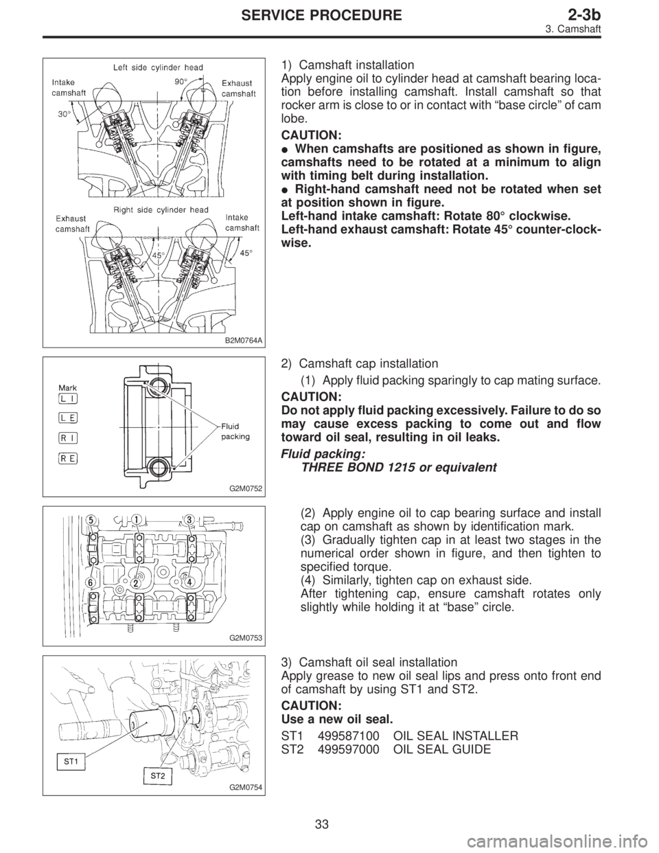
B2M0764A
1) Camshaft installation
Apply engine oil to cylinder head at camshaft bearing loca-
tion before installing camshaft. Install camshaft so that
rocker arm is close to or in contact with“base circle”of cam
lobe.
CAUTION:
�When camshafts are positioned as shown in figure,
camshafts need to be rotated at a minimum to align
with timing belt during installation.
�Right-hand camshaft need not be rotated when set
at position shown in figure.
Left-hand intake camshaft: Rotate 80°clockwise.
Left-hand exhaust camshaft: Rotate 45°counter-clock-
wise.
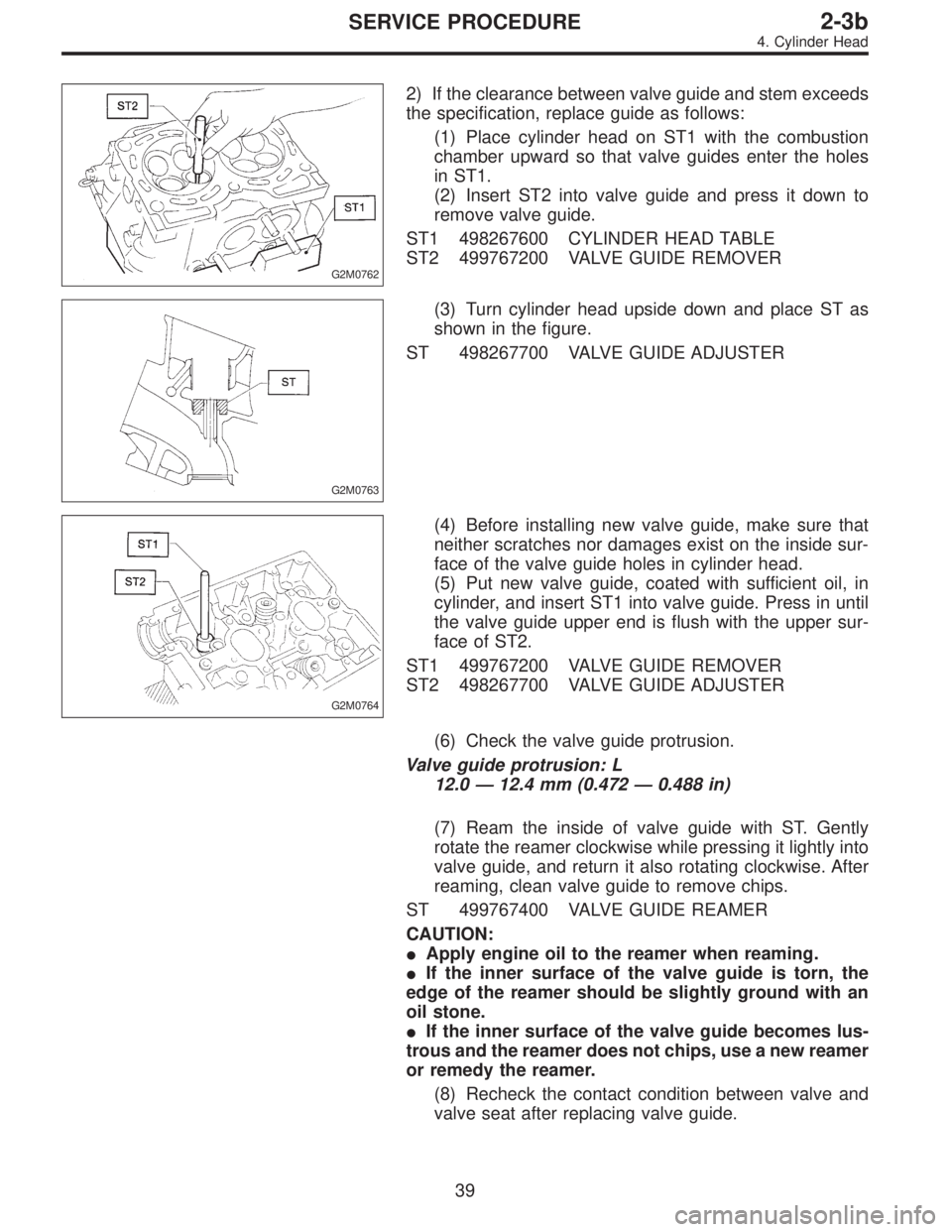
G2M0752
2) Camshaft cap installation
(1) Apply fluid packing sparingly to cap mating surface.
CAUTION:
Do not apply fluid packing excessively. Failure to do so
may cause excess packing to come out and flow
toward oil seal, resulting in oil leaks.
Fluid packing:
THREE BOND 1215 or equivalent
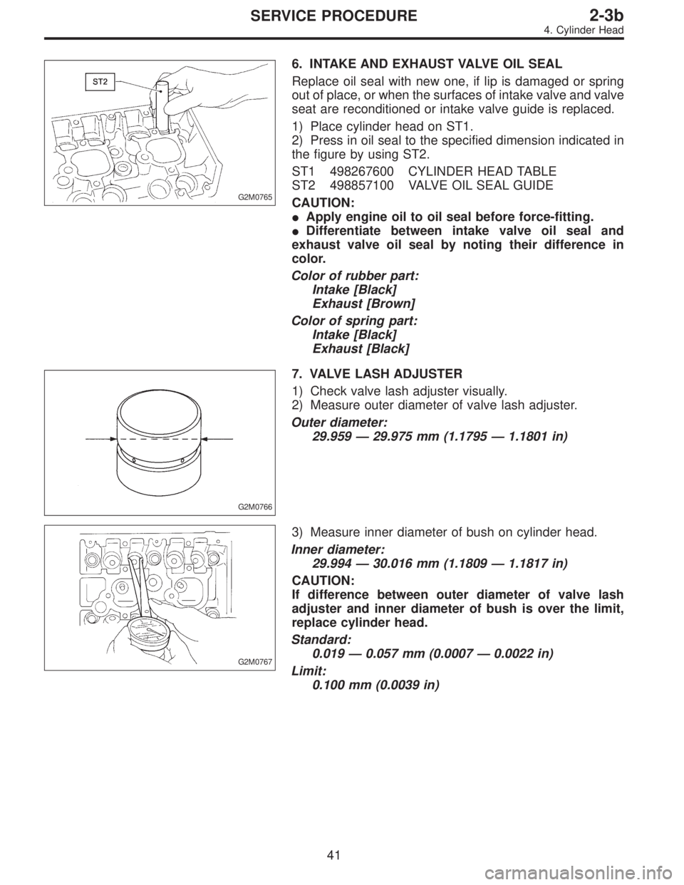
G2M0753
(2) Apply engine oil to cap bearing surface and install
cap on camshaft as shown by identification mark.
(3) Gradually tighten cap in at least two stages in the
numerical order shown in figure, and then tighten to
specified torque.
(4) Similarly, tighten cap on exhaust side.
After tightening cap, ensure camshaft rotates only
slightly while holding it at“base”circle.
G2M0754
3) Camshaft oil seal installation
Apply grease to new oil seal lips and press onto front end
of camshaft by using ST1 and ST2.
CAUTION:
Use a new oil seal.
ST1 499587100 OIL SEAL INSTALLER
ST2 499597000 OIL SEAL GUIDE
33
2-3bSERVICE PROCEDURE
3. Camshaft
Page 427 of 2890

G2M0762
2) If the clearance between valve guide and stem exceeds
the specification, replace guide as follows:
(1) Place cylinder head on ST1 with the combustion
chamber upward so that valve guides enter the holes
in ST1.
(2) Insert ST2 into valve guide and press it down to
remove valve guide.
ST1 498267600 CYLINDER HEAD TABLE
ST2 499767200 VALVE GUIDE REMOVER
G2M0763
(3) Turn cylinder head upside down and place ST as
shown in the figure.
ST 498267700 VALVE GUIDE ADJUSTER
G2M0764
(4) Before installing new valve guide, make sure that
neither scratches nor damages exist on the inside sur-
face of the valve guide holes in cylinder head.
(5) Put new valve guide, coated with sufficient oil, in
cylinder, and insert ST1 into valve guide. Press in until
the valve guide upper end is flush with the upper sur-
face of ST2.
ST1 499767200 VALVE GUIDE REMOVER
ST2 498267700 VALVE GUIDE ADJUSTER
(6) Check the valve guide protrusion.
Valve guide protrusion: L
12.0—12.4 mm (0.472—0.488 in)
(7) Ream the inside of valve guide with ST. Gently
rotate the reamer clockwise while pressing it lightly into
valve guide, and return it also rotating clockwise. After
reaming, clean valve guide to remove chips.
ST 499767400 VALVE GUIDE REAMER
CAUTION:
�Apply engine oil to the reamer when reaming.
�If the inner surface of the valve guide is torn, the
edge of the reamer should be slightly ground with an
oil stone.
�If the inner surface of the valve guide becomes lus-
trous and the reamer does not chips, use a new reamer
or remedy the reamer.
(8) Recheck the contact condition between valve and
valve seat after replacing valve guide.
39
2-3bSERVICE PROCEDURE
4. Cylinder Head
Page 429 of 2890

G2M0765
6. INTAKE AND EXHAUST VALVE OIL SEAL
Replace oil seal with new one, if lip is damaged or spring
out of place, or when the surfaces of intake valve and valve
seat are reconditioned or intake valve guide is replaced.
1) Place cylinder head on ST1.
2) Press in oil seal to the specified dimension indicated in
the figure by using ST2.
ST1 498267600 CYLINDER HEAD TABLE
ST2 498857100 VALVE OIL SEAL GUIDE
CAUTION:
�Apply engine oil to oil seal before force-fitting.
�Differentiate between intake valve oil seal and
exhaust valve oil seal by noting their difference in
color.
Color of rubber part:
Intake [Black]
Exhaust [Brown]
Color of spring part:
Intake [Black]
Exhaust [Black]
G2M0766
7. VALVE LASH ADJUSTER
1) Check valve lash adjuster visually.
2) Measure outer diameter of valve lash adjuster.
Outer diameter:
29.959—29.975 mm (1.1795—1.1801 in)
G2M0767
3) Measure inner diameter of bush on cylinder head.
Inner diameter:
29.994—30.016 mm (1.1809—1.1817 in)
CAUTION:
If difference between outer diameter of valve lash
adjuster and inner diameter of bush is over the limit,
replace cylinder head.
Standard:
0.019—0.057 mm (0.0007—0.0022 in)
Limit:
0.100 mm (0.0039 in)
41
2-3bSERVICE PROCEDURE
4. Cylinder Head
Page 430 of 2890
D: ASSEMBLY
G2M0768
G2M0759
1) Installation of valve spring and valve
(1) Coat stem of each valve with engine oil and insert
valve into valve guide.
CAUTION:
When inserting valve into valve guide, use special care
not to damage the oil seal lip.
(2) Set cylinder head on ST1.
(3) Install valve spring and retainer using ST2.
ST1 498267600 CYLINDER HEAD TABLE
ST2 499718000 VALVE SPRING REMOVER
CAUTION:
Be sure to install the valve springs with their close-
coiled end facing the seat on the cylinder head.
(4) Compress valve spring and fit valve spring retainer
key.
(5) After installing, tap valve spring retainers lightly
with wooden hammer for better seating.
2) Install hydraulic lash adjuster.
42
2-3bSERVICE PROCEDURE
4. Cylinder Head
Page 431 of 2890
E: INSTALLATION
1. CYLINDER HEAD
B2M0771A
1) Install cylinder head and gaskets on cylinder block.
CAUTION:
Use new cylinder head gaskets.
G2M0771
2) Tighten cylinder head bolts.
(1) Apply a coat of engine oil to washers and bolt
threads.
(2) Tighten all bolts to 29 N⋅m (3.0 kg-m, 22 ft-lb) in
numerical sequence.
Then tighten all bolts to 69 N⋅m (7.0 kg-m, 51 ft-lb) in
numerical sequence.
(3) Back off all bolts by 180°first; back them off by 180°
again.
(4) Tighten bolts�
1and�2to 34 N⋅m (3.5 kg-m, 25 ft-
lb).
(5) Tighten bolts�
3,�4,�5and�6to 15 N⋅m (1.5 kg-m,
11 ft-lb).
(6) Tighten all bolts by 80 to 90°in numerical
sequence.
CAUTION:
Do not tighten bolts more than 90°.
43
2-3bSERVICE PROCEDURE
4. Cylinder Head
Page 438 of 2890
2. OIL PUMP AND ENGINE COOLANT PUMP
B2M0705A
1) Remove housing cover.
50
2-3bSERVICE PROCEDURE
5. Cylinder Block
Page 439 of 2890
B2M0706A
2) Remove drive plate.
To lock crankshaft use ST.
ST 498497100 CRANKSHAFT STOPPER
3) Remove oil separator cover.
4) Remove engine coolant pipe.
5) Remove engine coolant pump.
G2M0162
6) Remove oil pump from cylinder block.
Use a flat-bladed screwdriver as shown in Figure when
removing oil pump.
CAUTION:
Be careful not to scratch the mating surface of cylin-
der block and oil pump.
G2M0163
7) Removal of oil pan
(1) Turn cylinder block with #2 and #4 piston sides
facing upward.
(2) Remove bolts which secure oil pan to cylinder
block.
(3) Insert a oil pan cutter blade between cylinder block-
to-oil pan clearance and remove oil pan.
CAUTION:
Do not use a screwdriver or similar tool in place of oil-
pan cutter.
8) Remove oil strainer stay.
9) Remove oil strainer.
10) Remove baffle plate.
11) Remove oil filter.
51
2-3bSERVICE PROCEDURE
5. Cylinder Block